Game Gear VA1 - 1
Console status
| Date | Power | Sound | RLB | Game operation | Screen |
|---|---|---|---|---|---|
| 2026/04/09 | ✔️ | ⚠️ | ✔️ | ✔️ | ⚠️ |
| 2026/04/10 | ⚠️ | ⚠️ | ✔️ | ✔️ | ⚠️ |
Console details
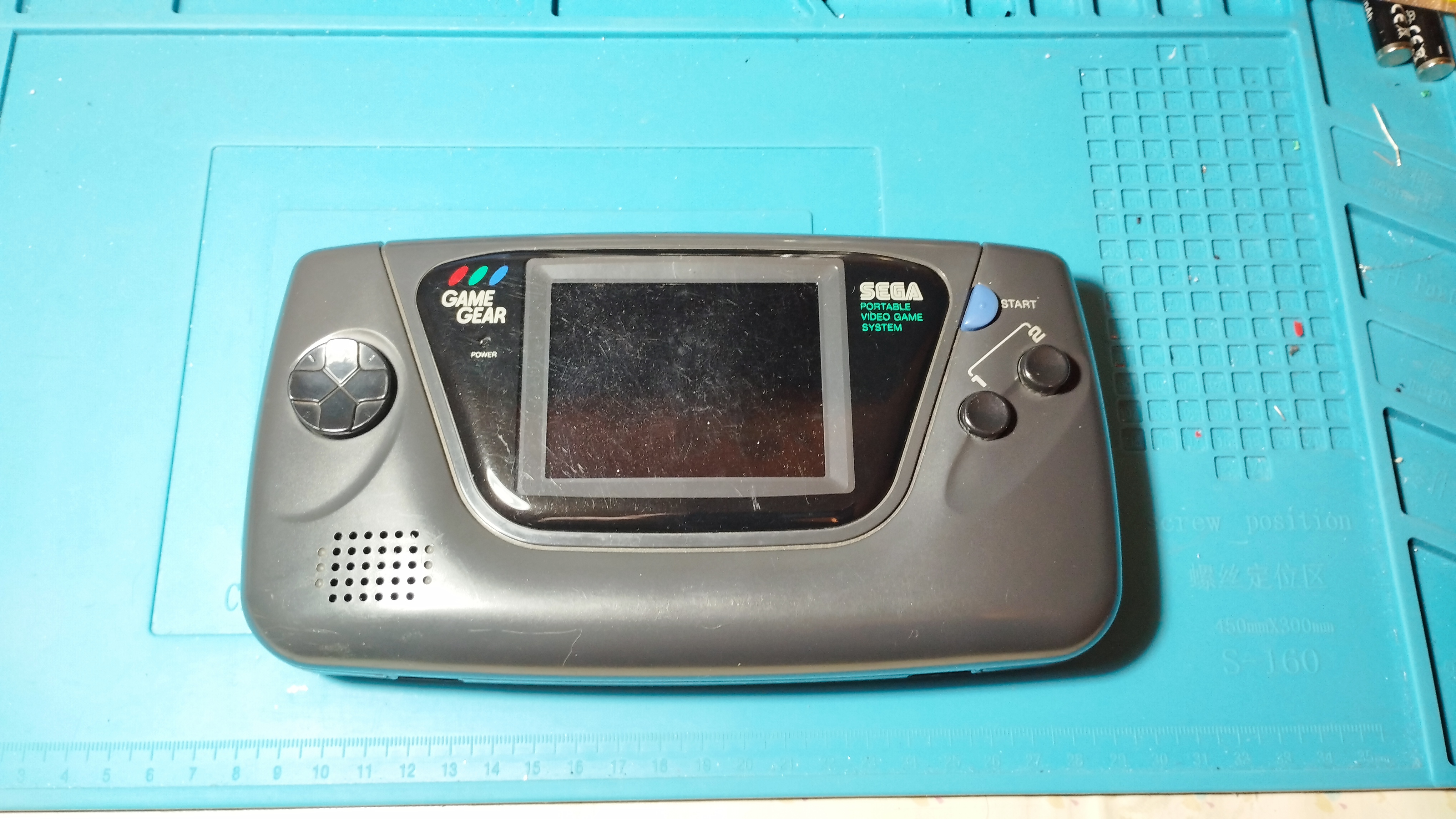
- Japanese Game Gear bought during my trip to Japan on August 2023
Specs
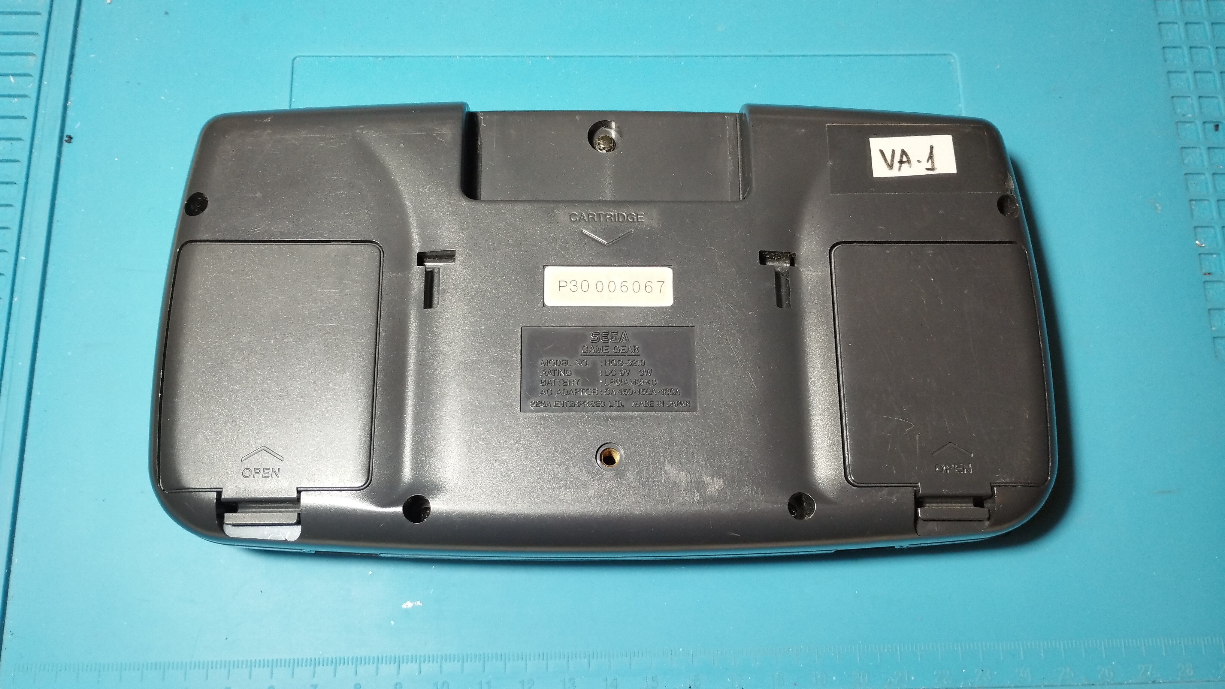
- Model Number: HGG-3210
- Serial Number: P30006067
- Main board: 837-8560 (Single ASIC)
- Power board: ???
- Audio board: 837-8562
Overview
First boot
Power LED turns on (RLB)
Backlight turns on and there’s a dim image in the screen
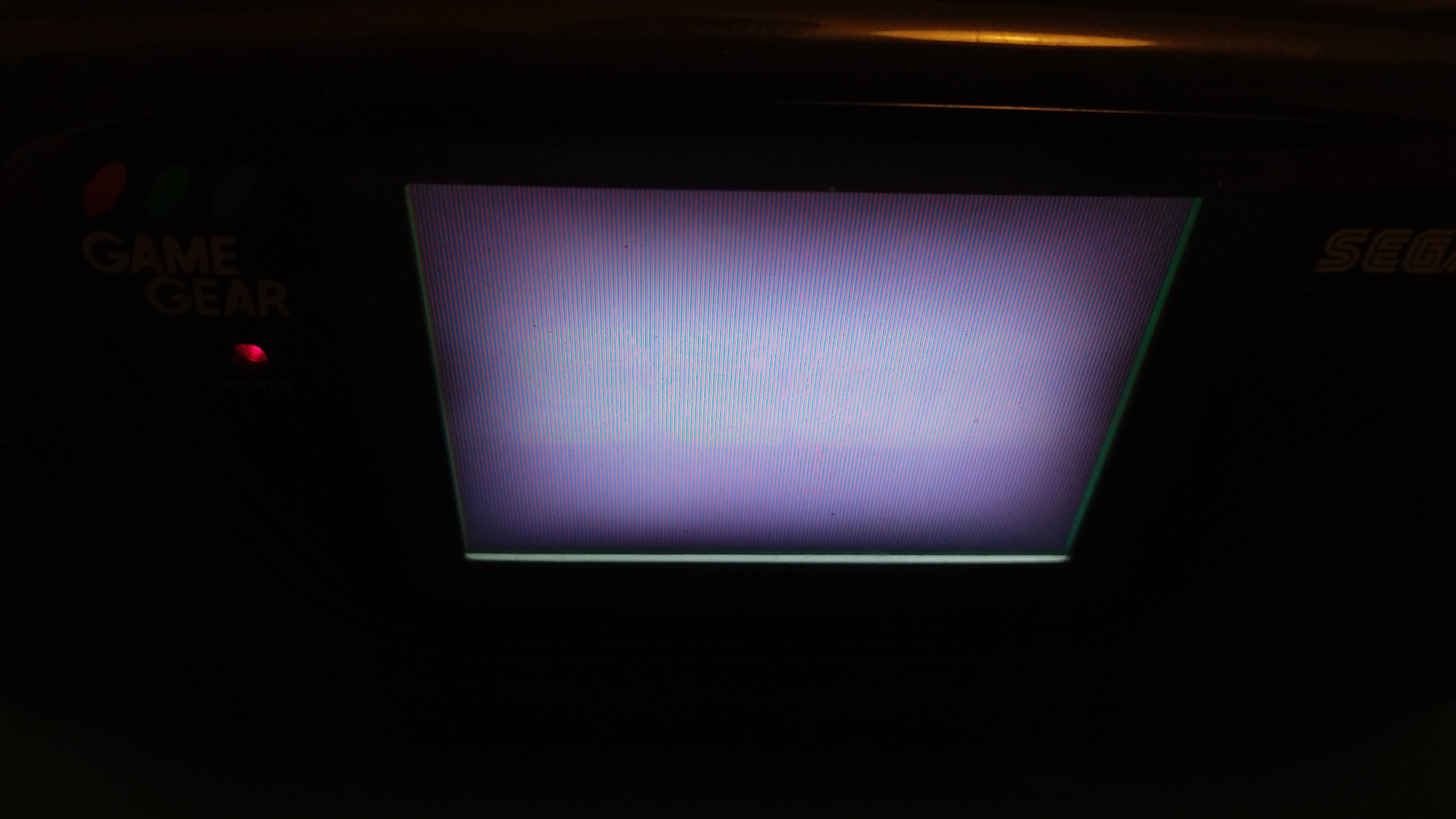
Game Gear - Dim image 1 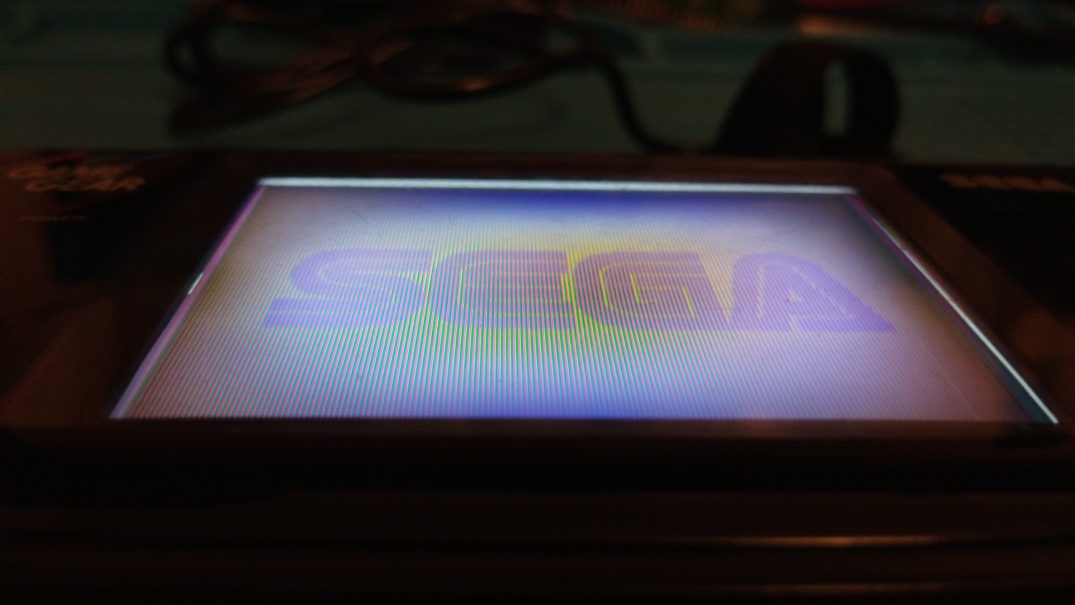
Game Gear - Dim image 2 Audio doesn’t work
Visual inspection
Outside
The outside has visible scratches from usage but no cracks
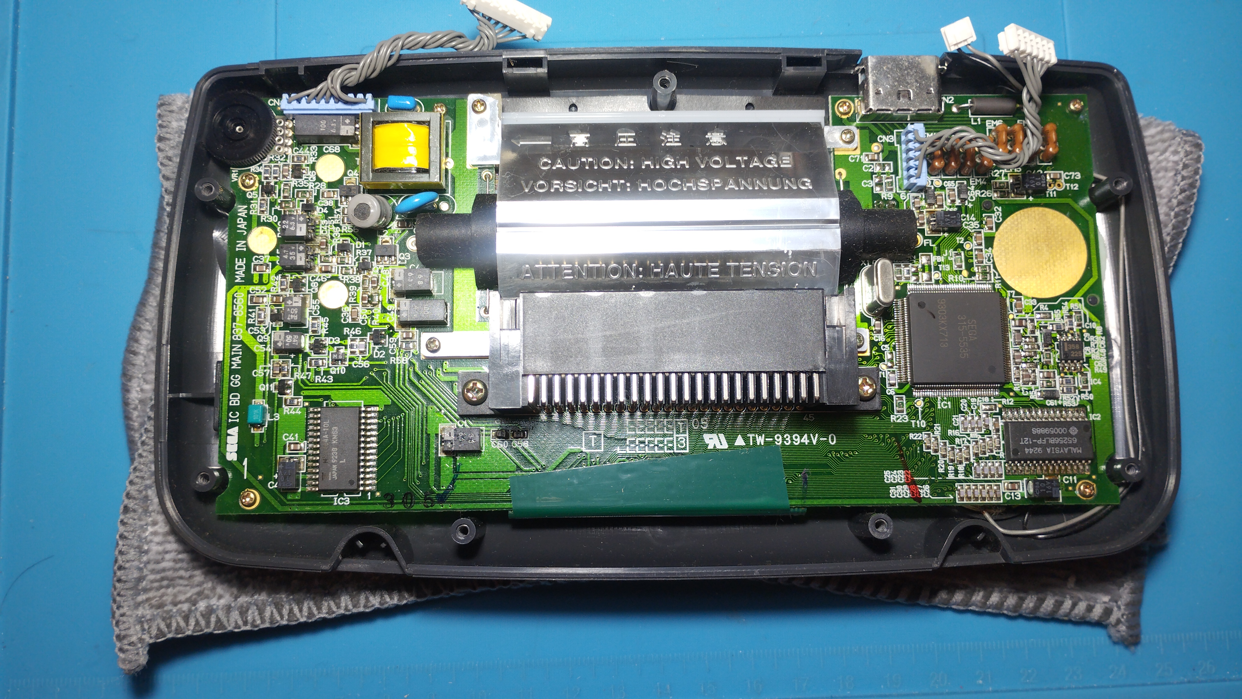
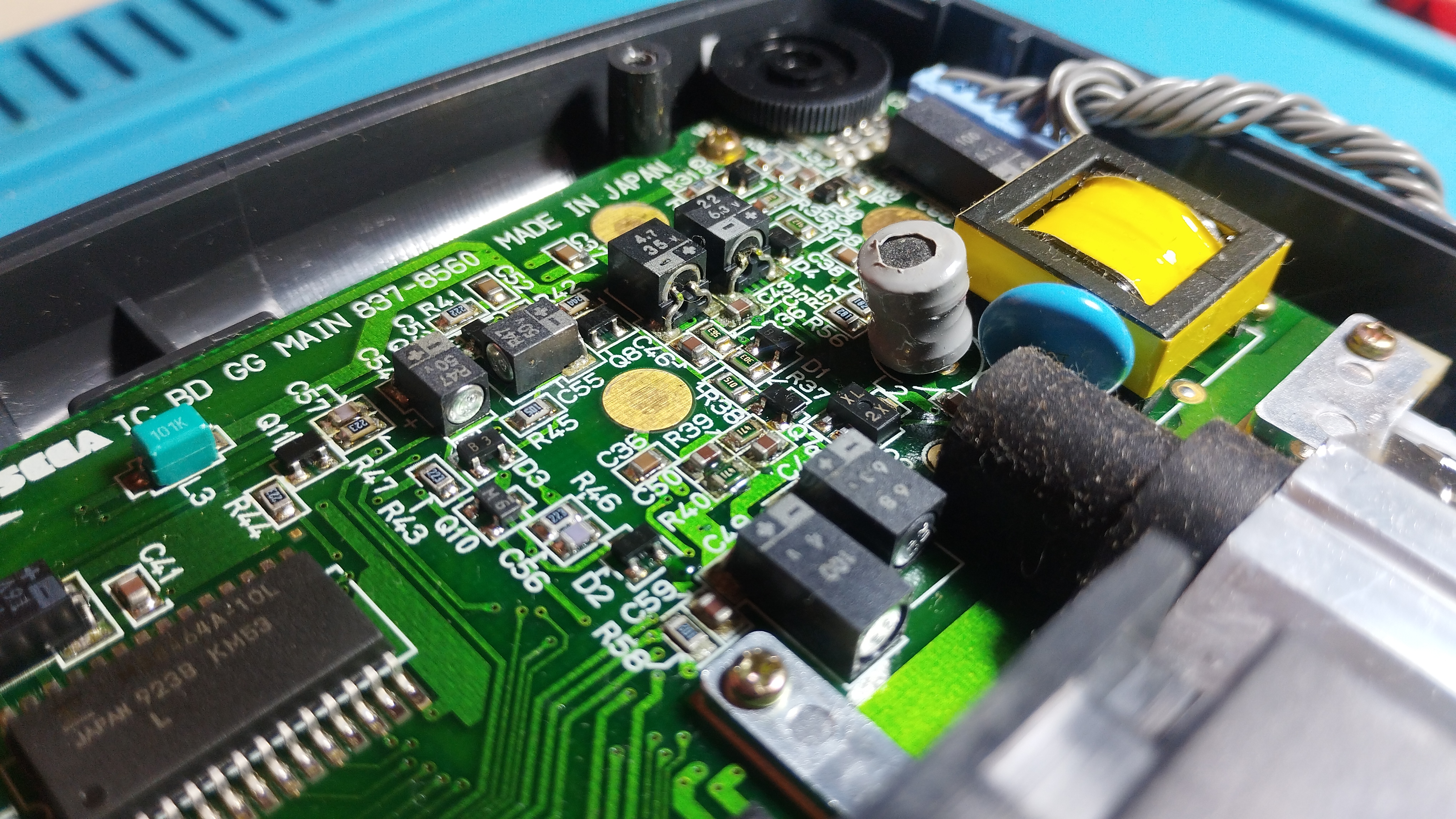
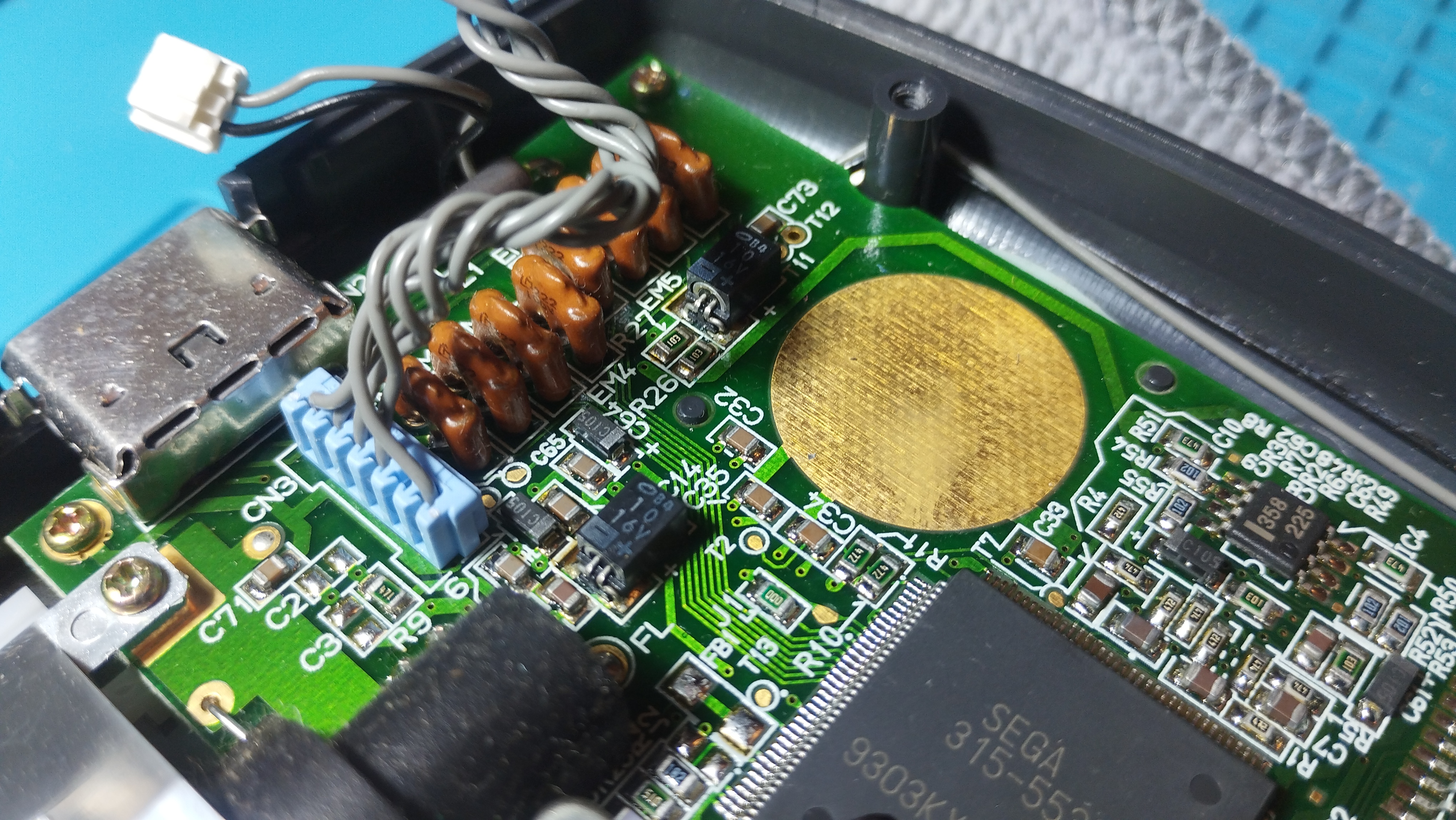
Main board
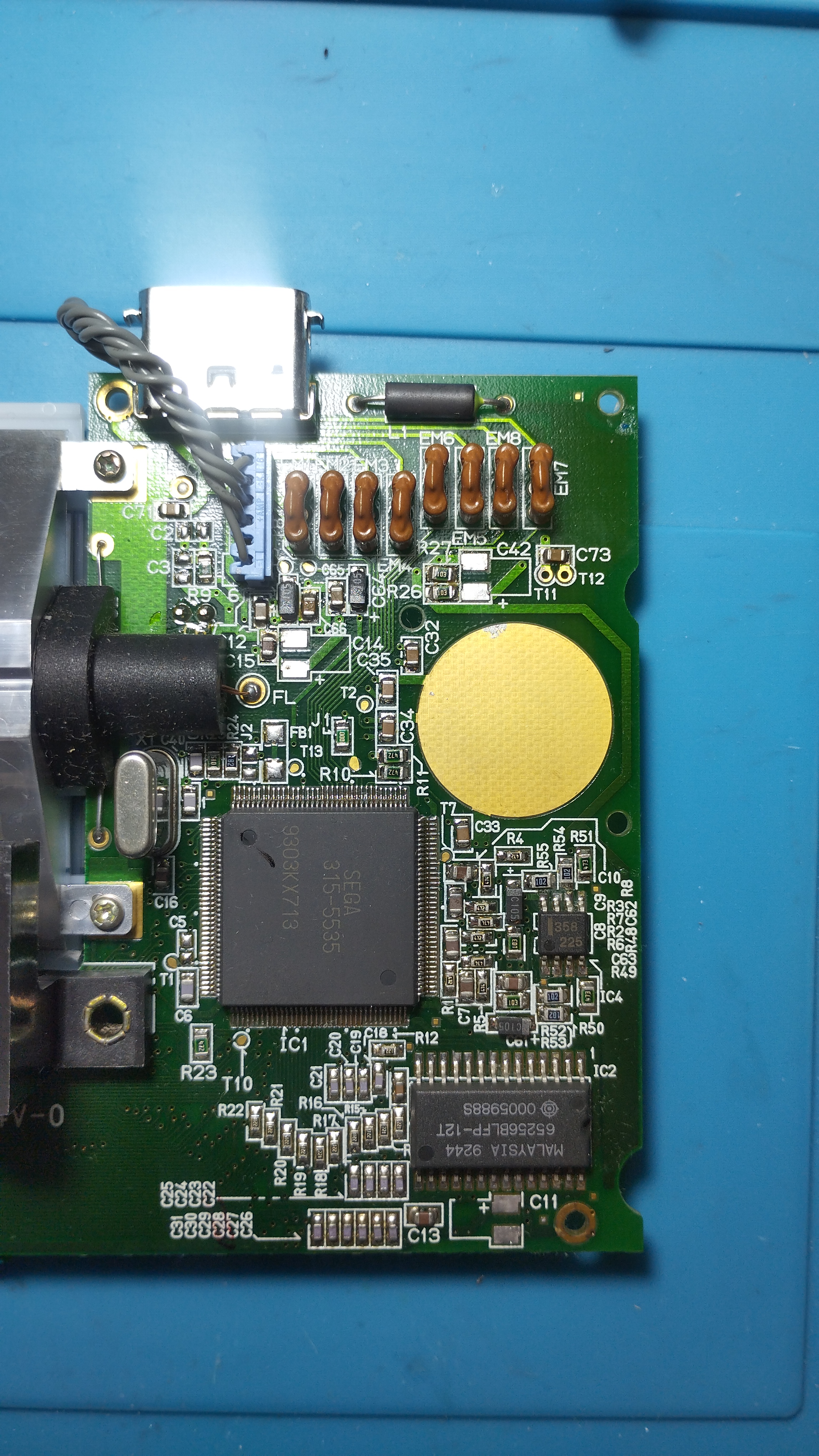
Front side
Some flux residues from factory:
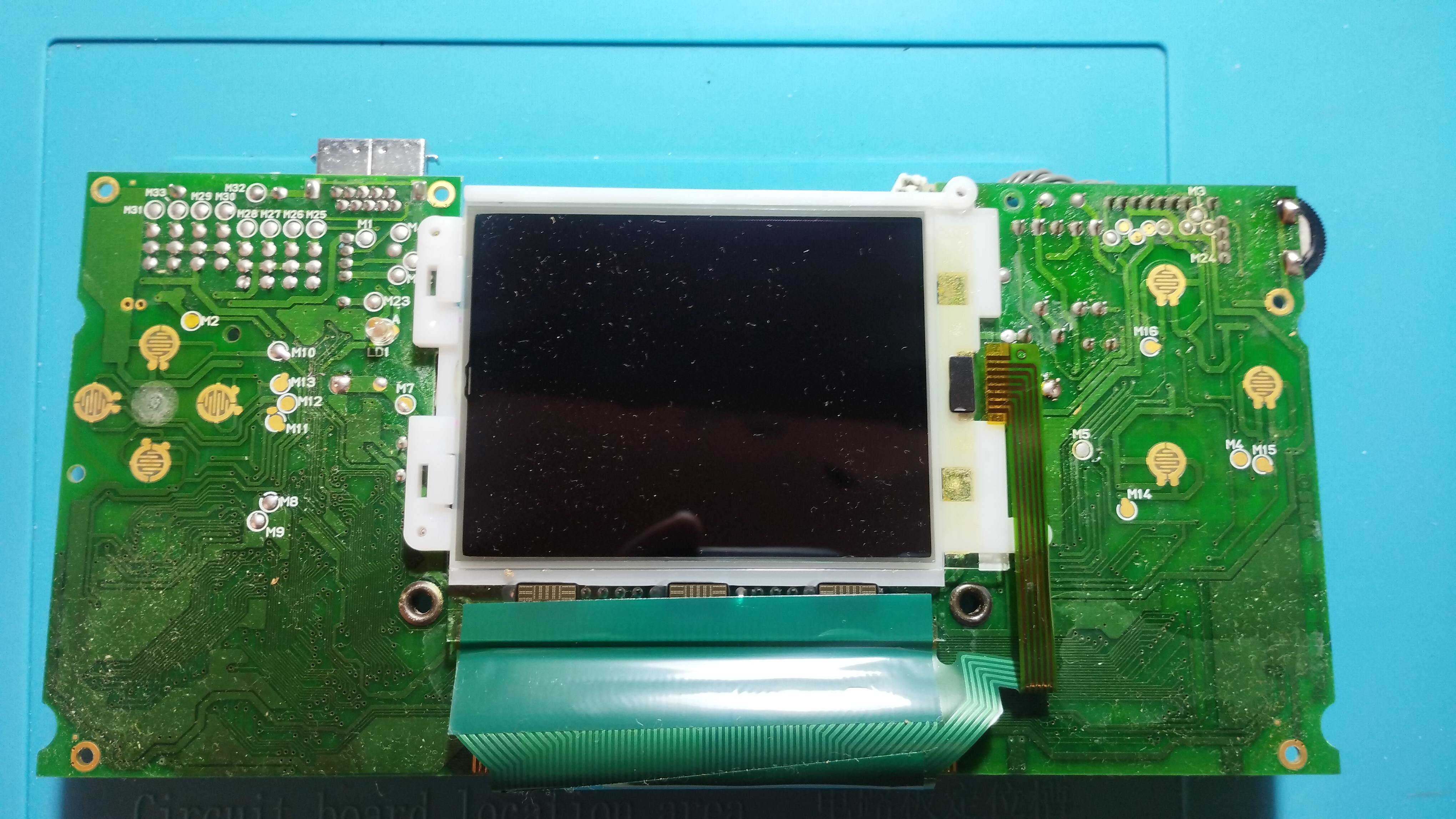
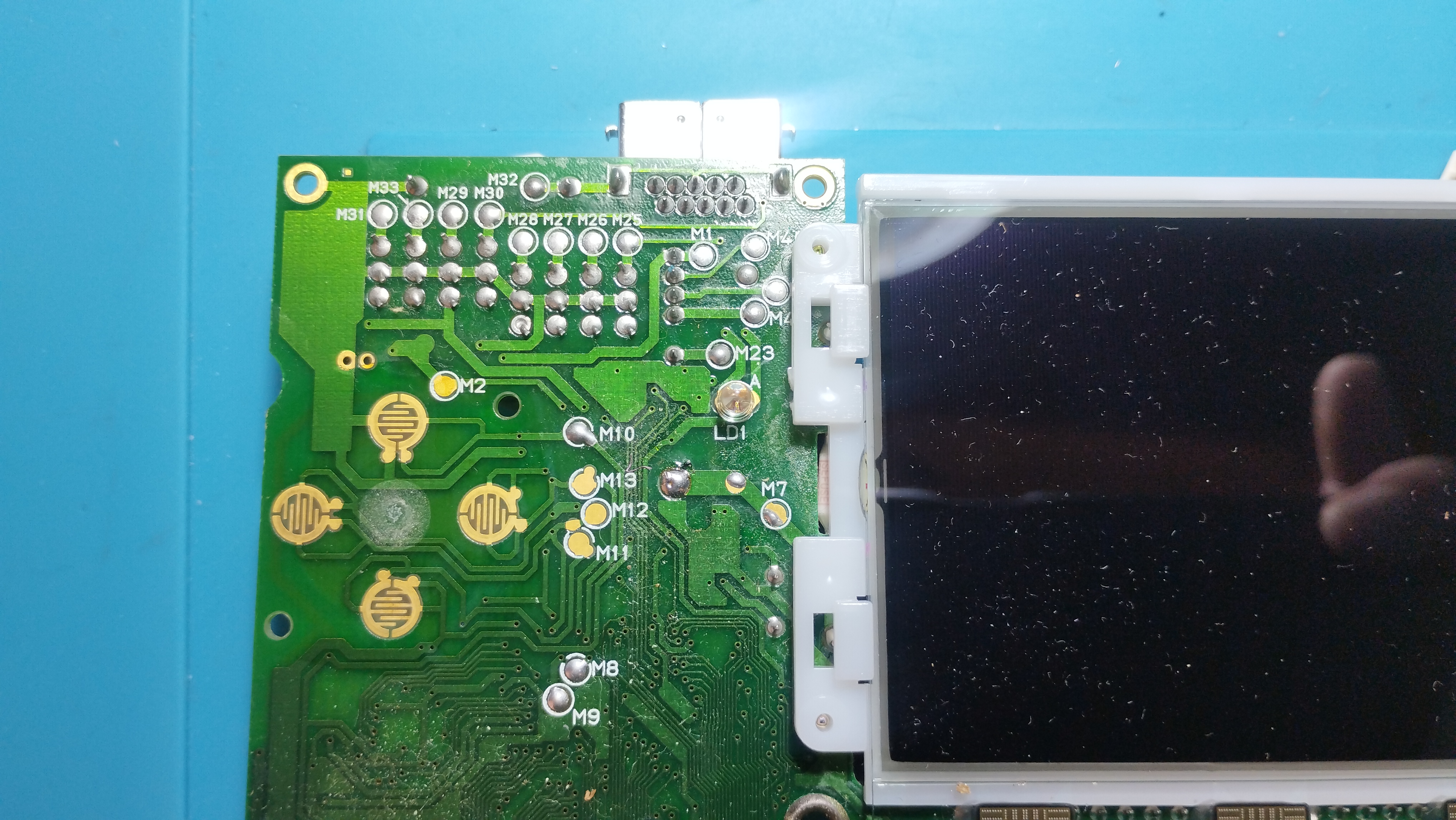
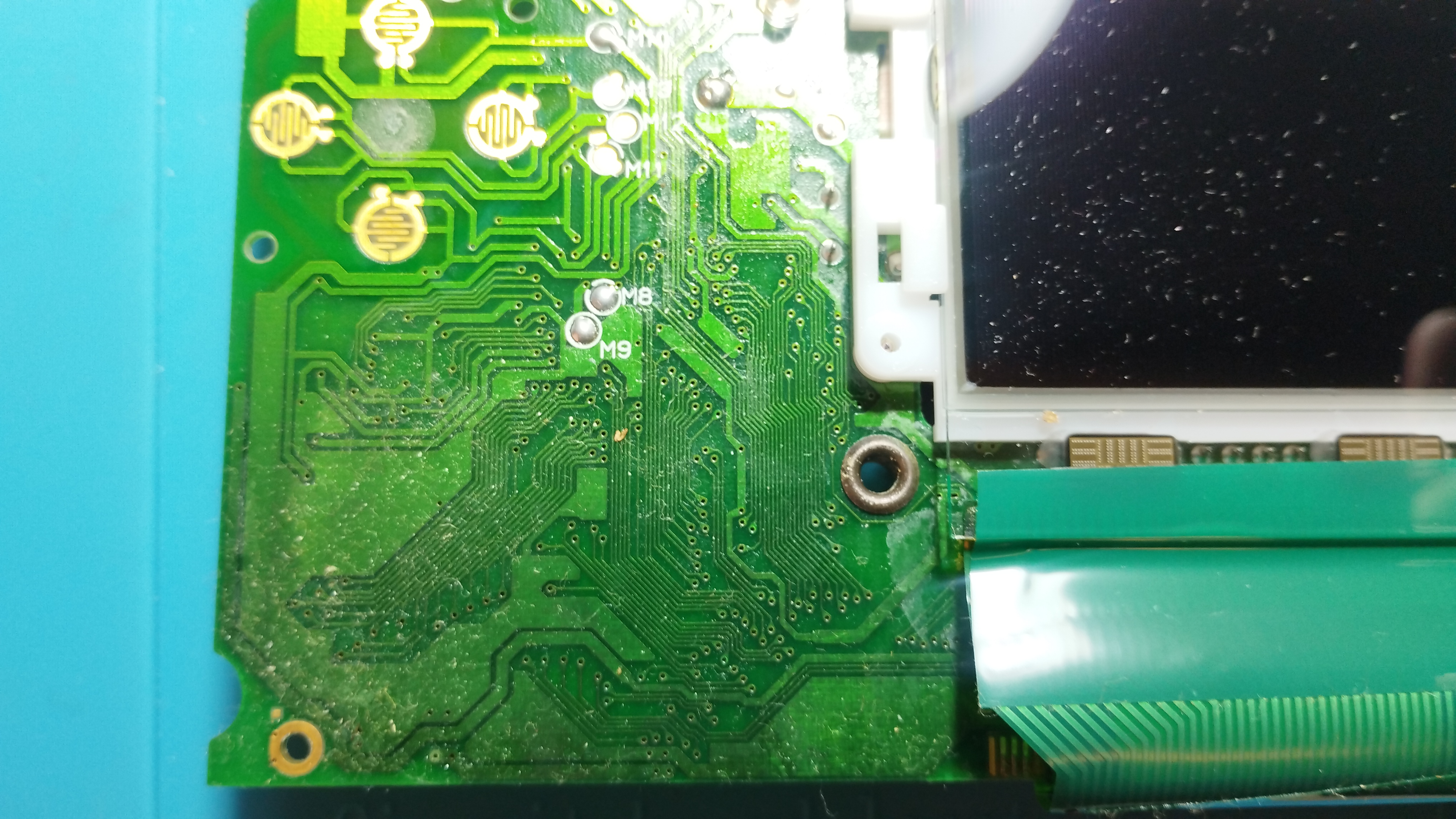
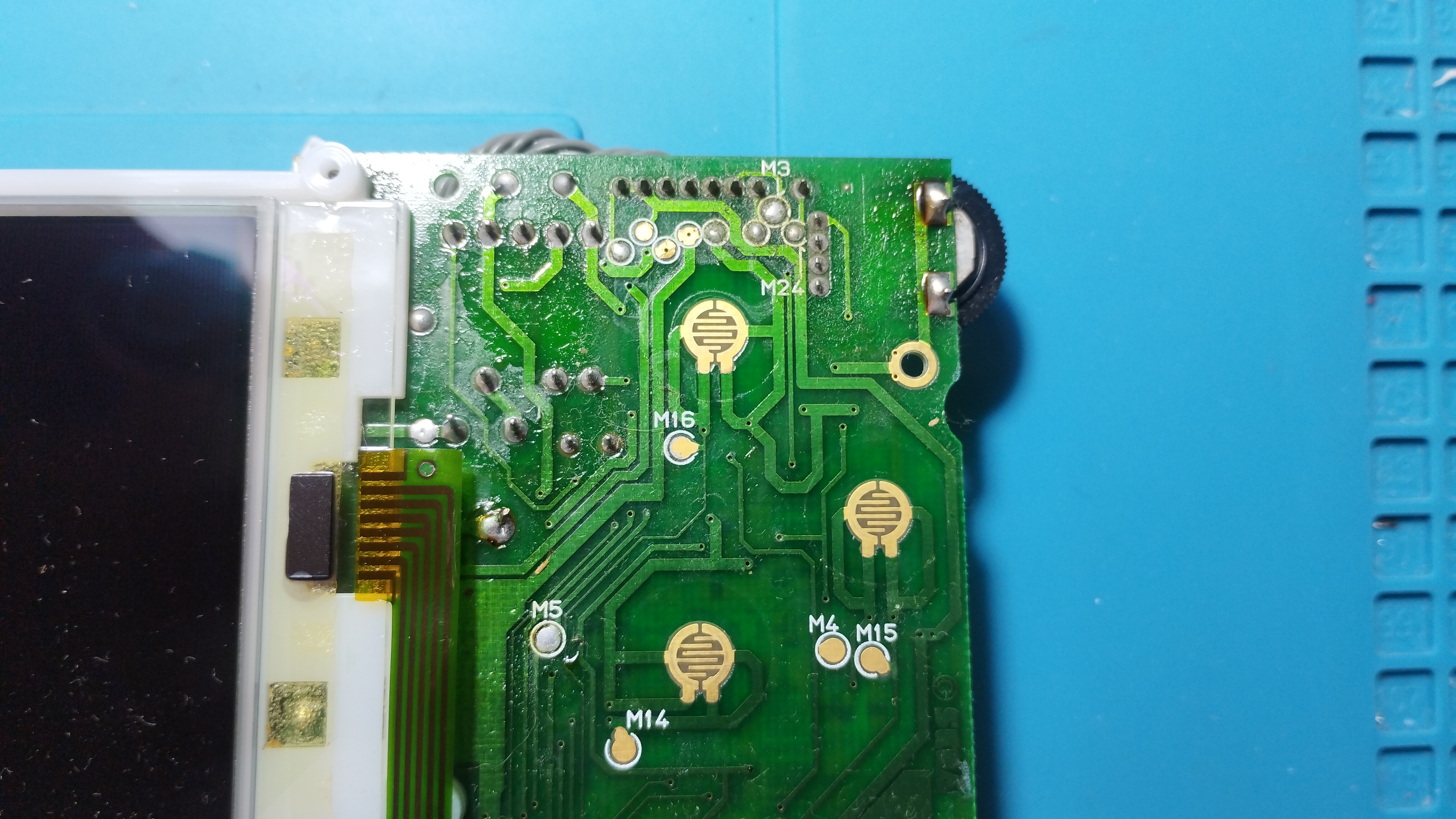
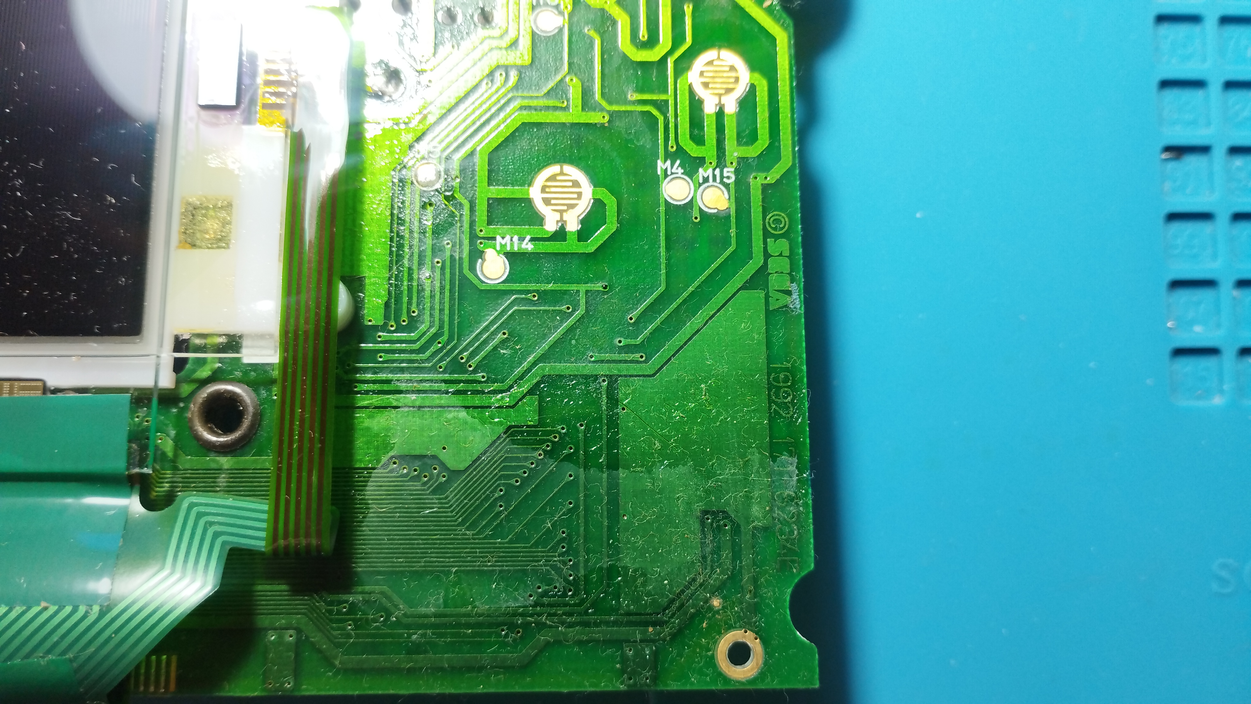
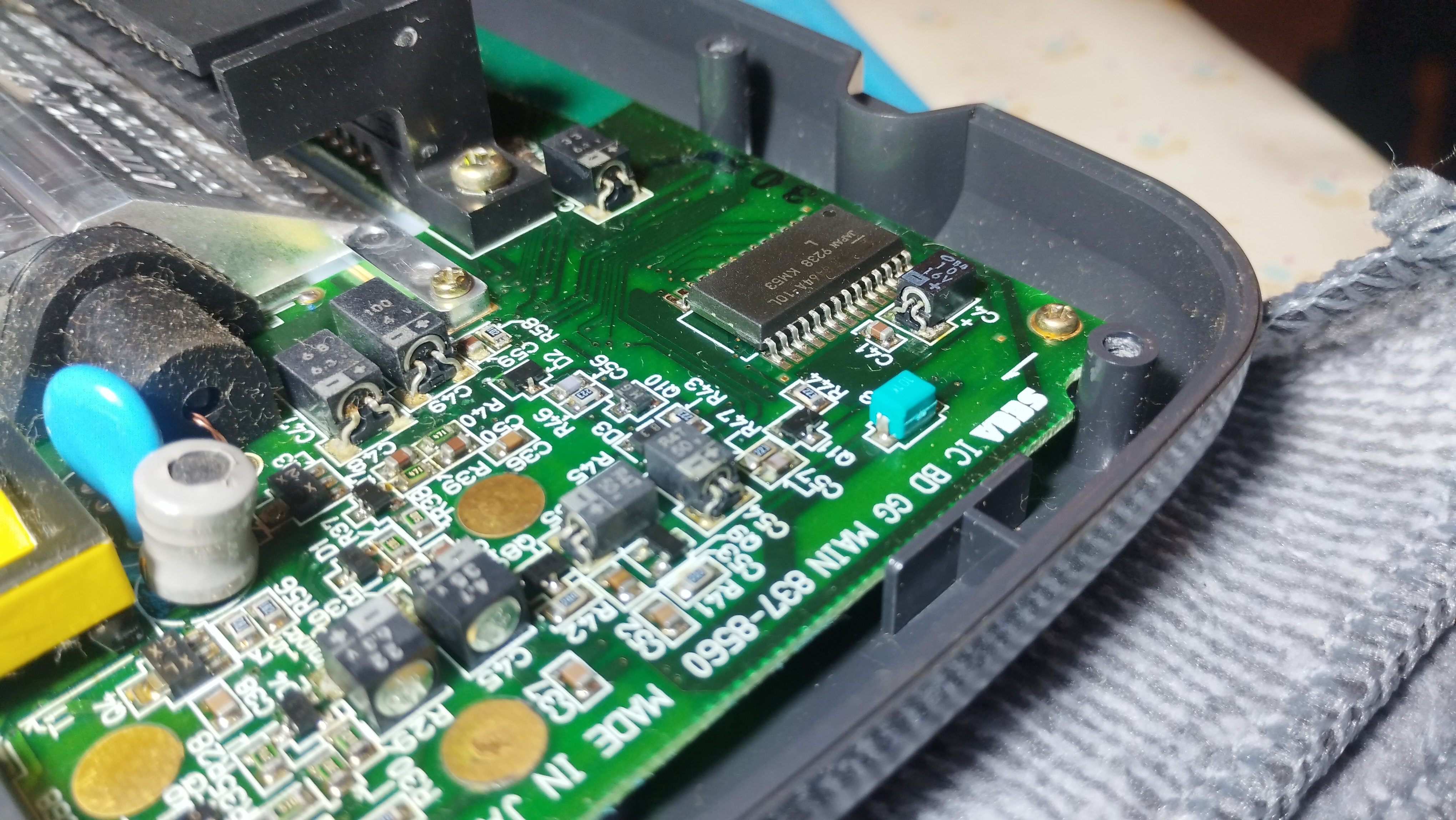
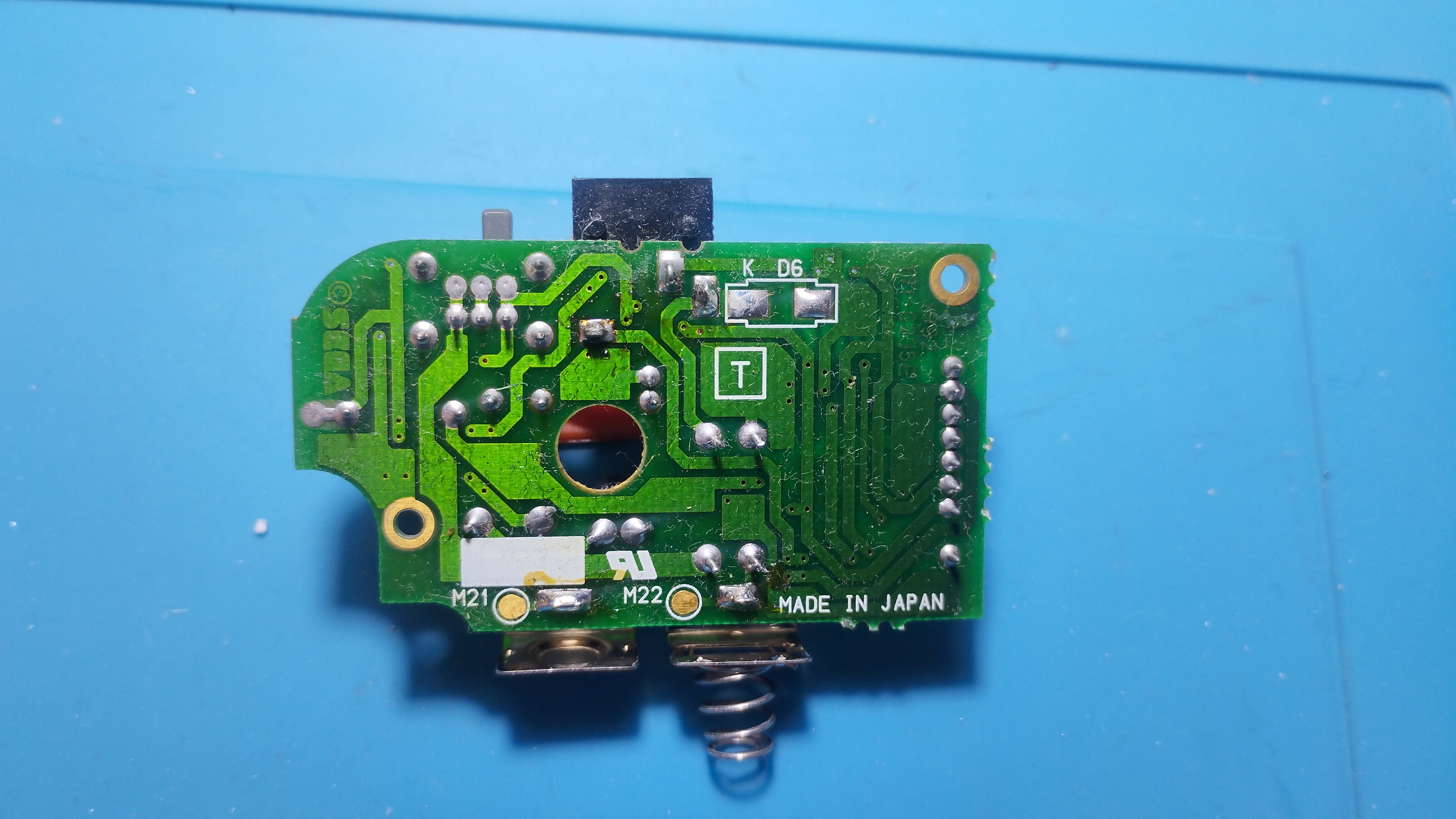
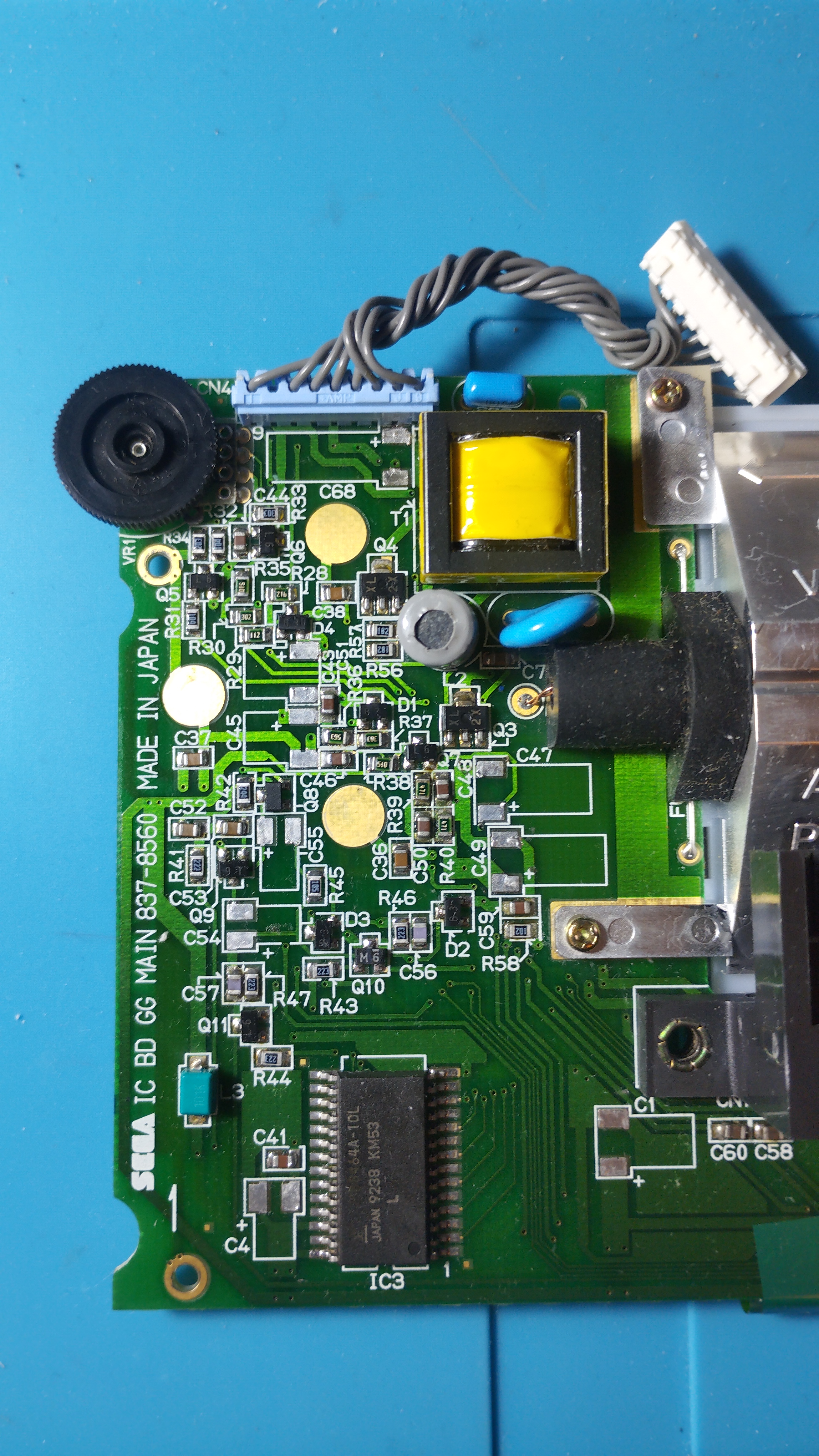
Rear side
There are visible leaks on capacitors, so extreme precautions when removing and cleaning the pads:
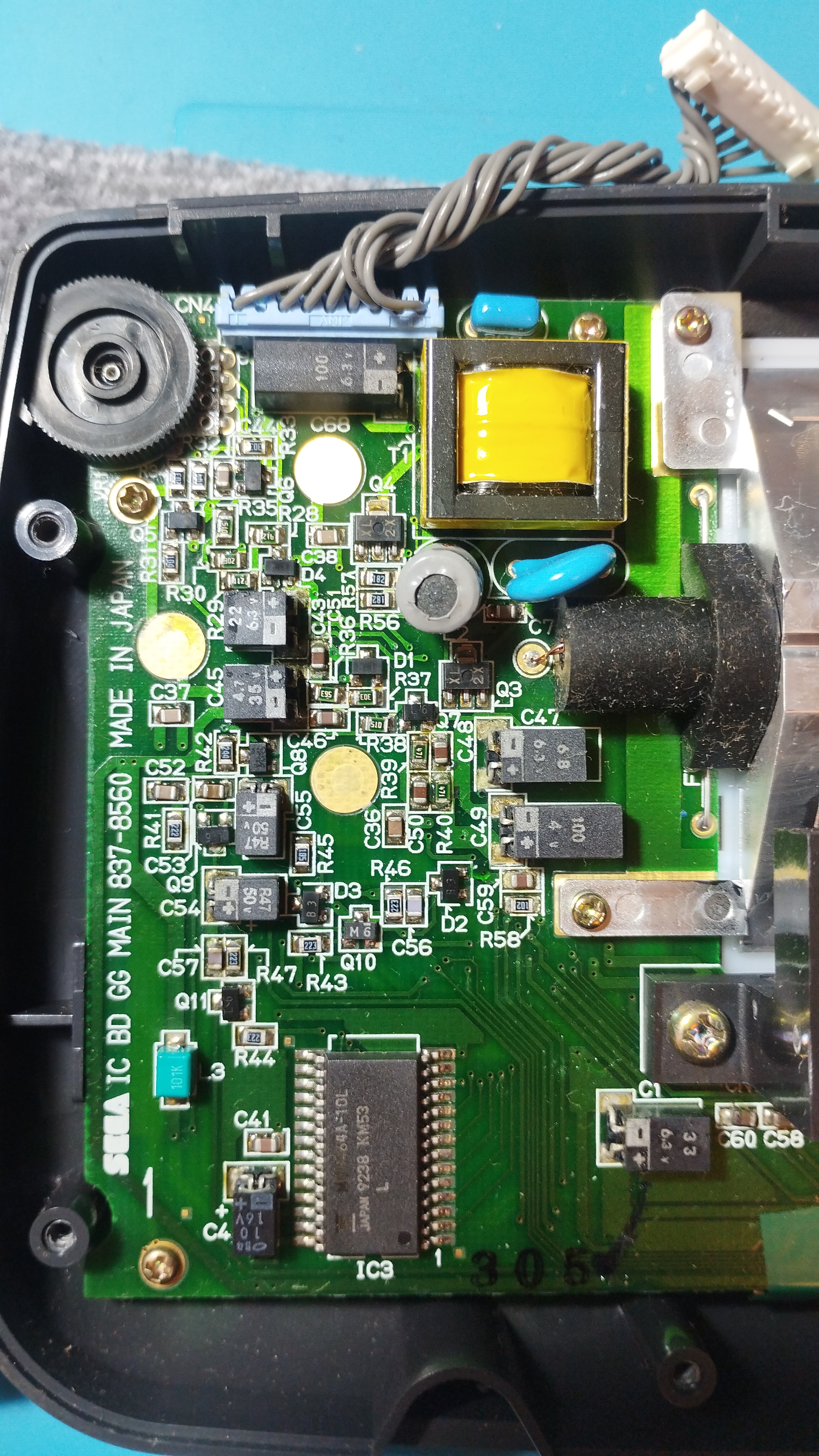
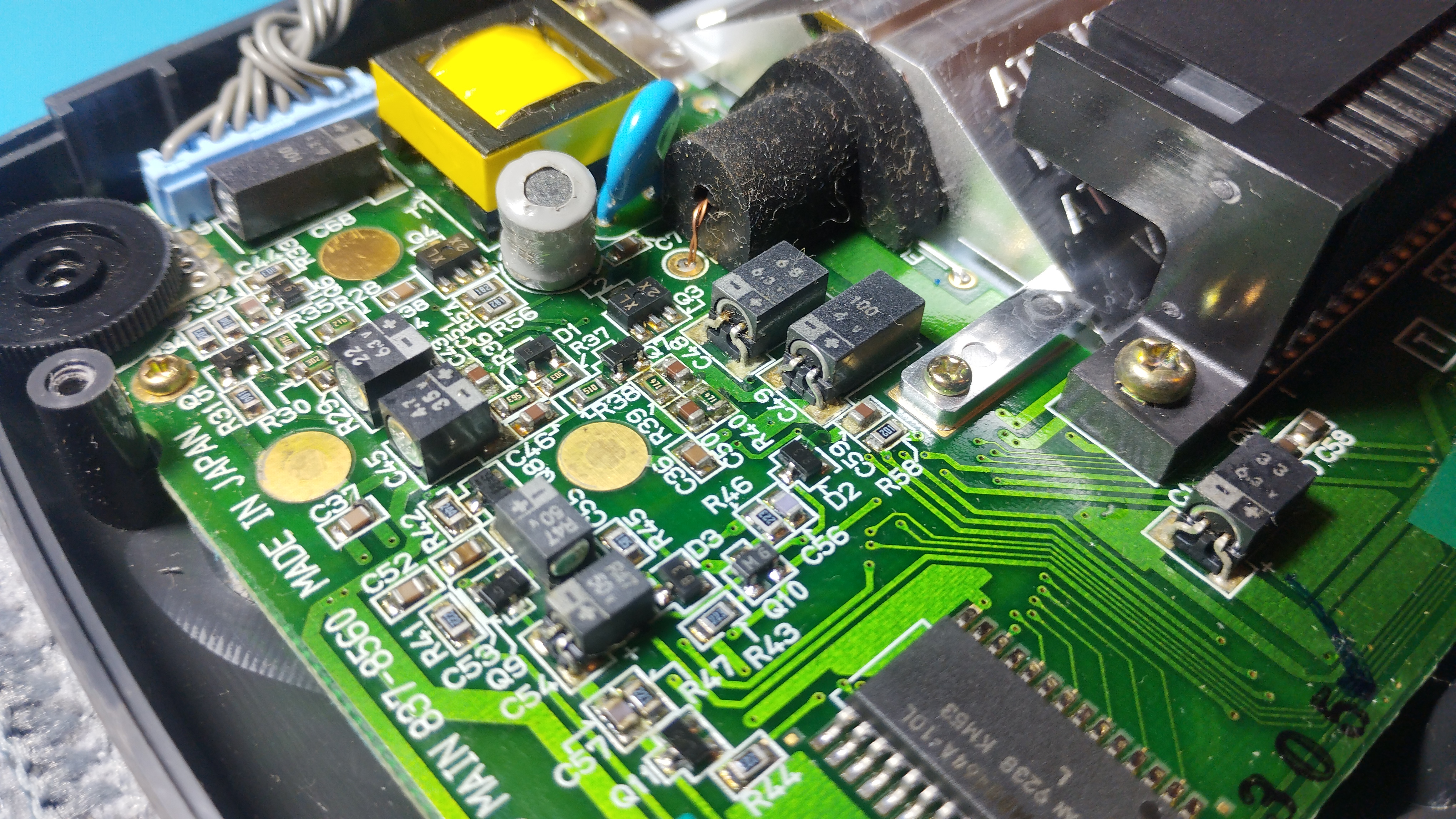
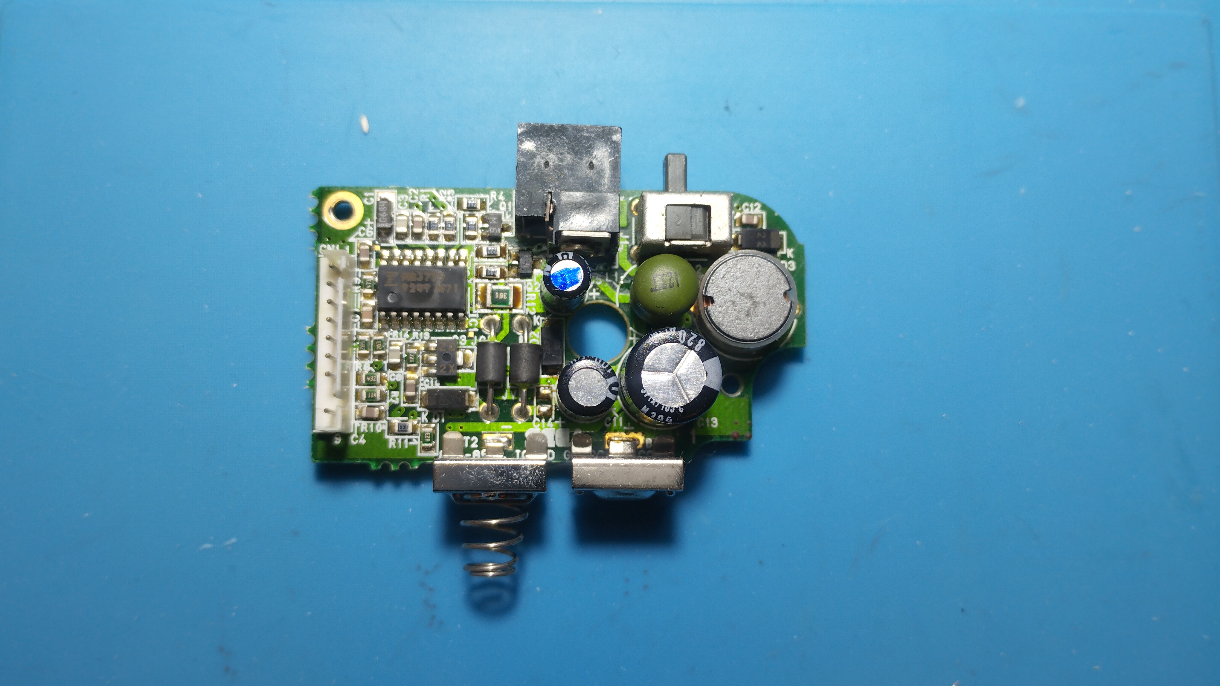
Power board
Power board seems pretty clean and outputs expected voltages:
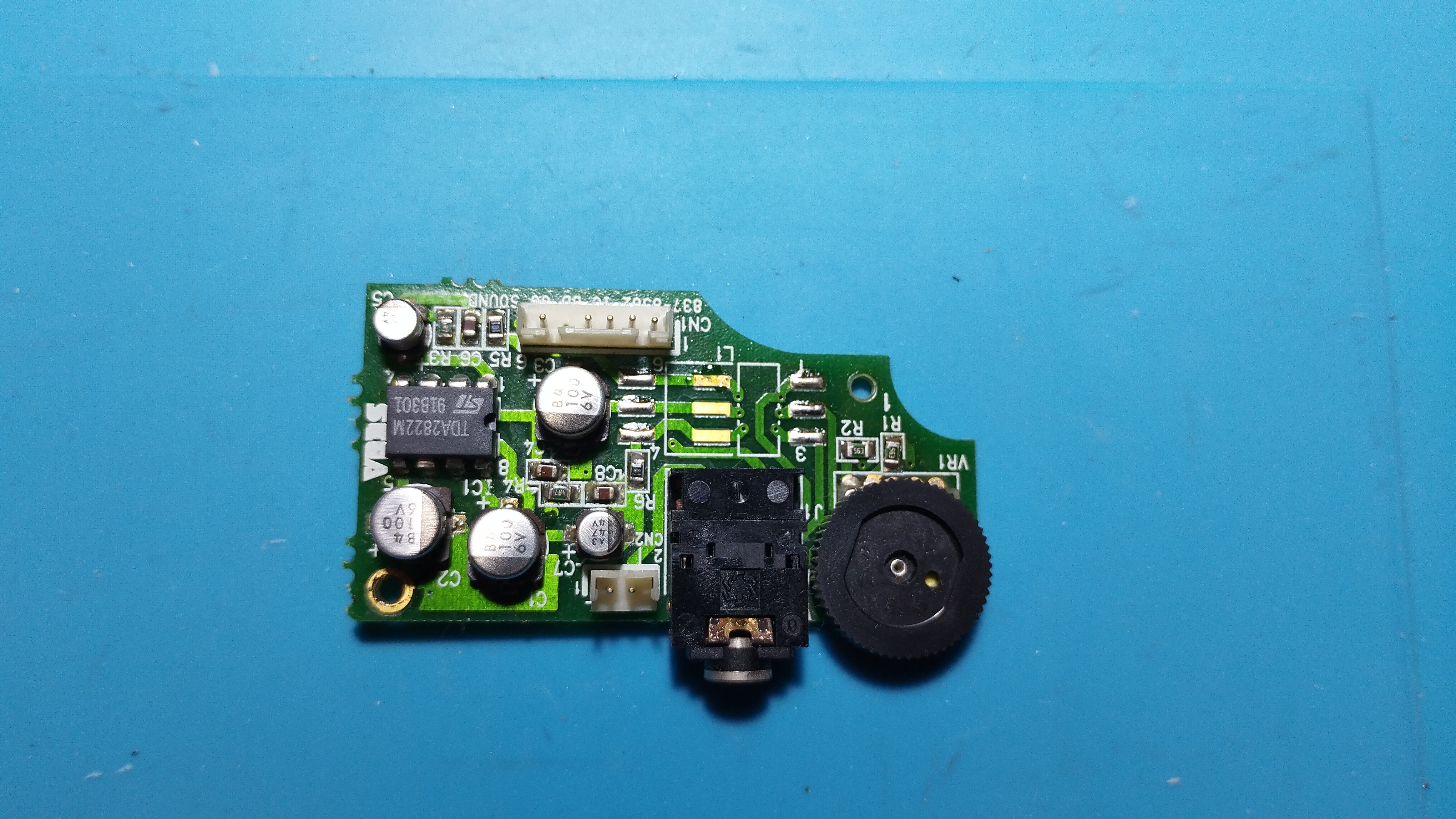
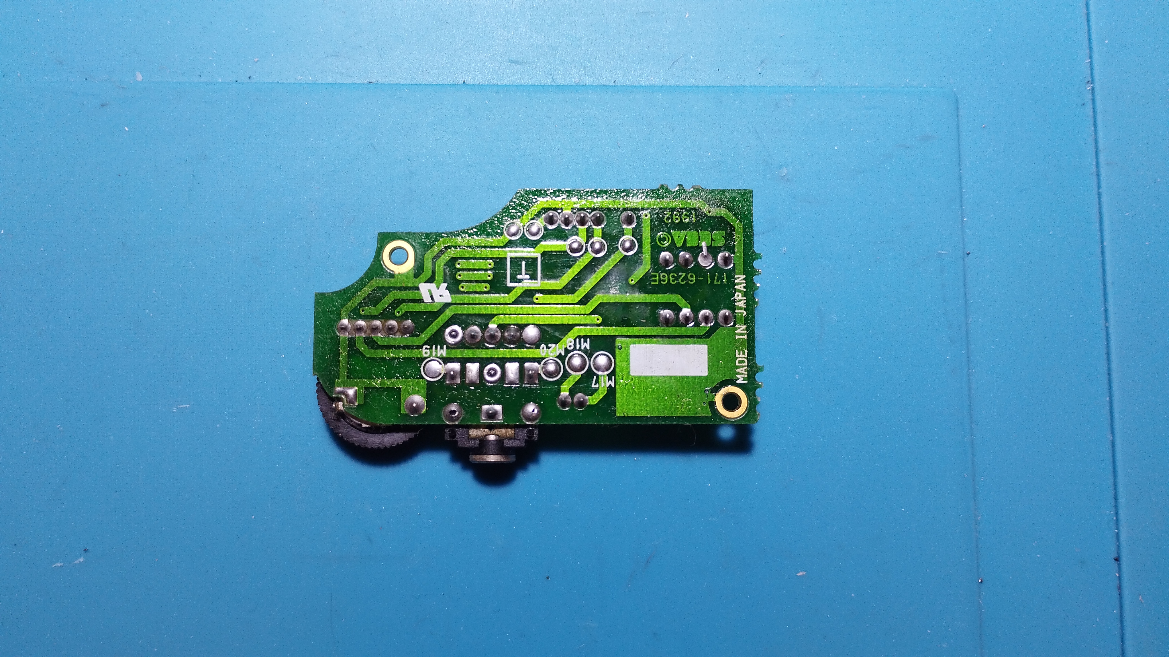
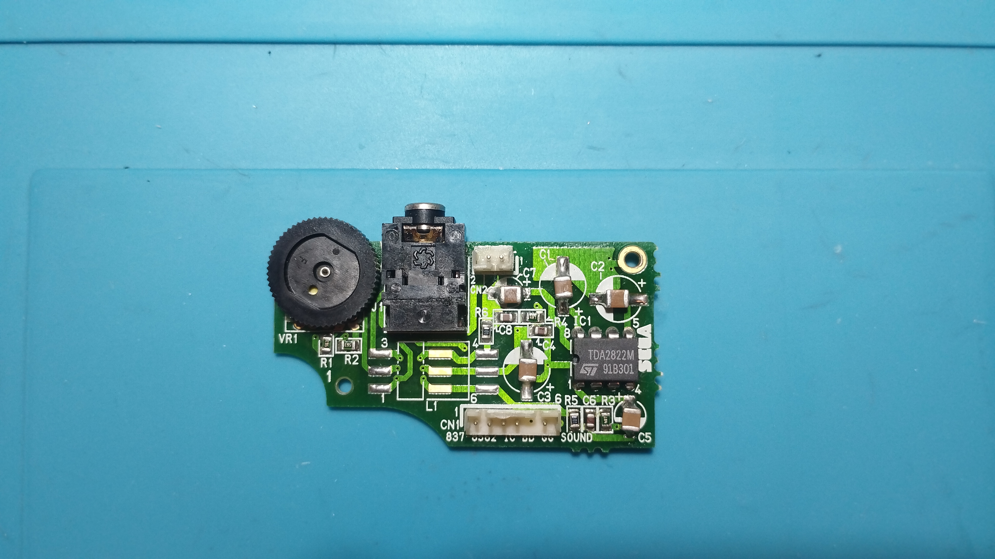
Audio board
Visible leakage and corrosion in some contacts.
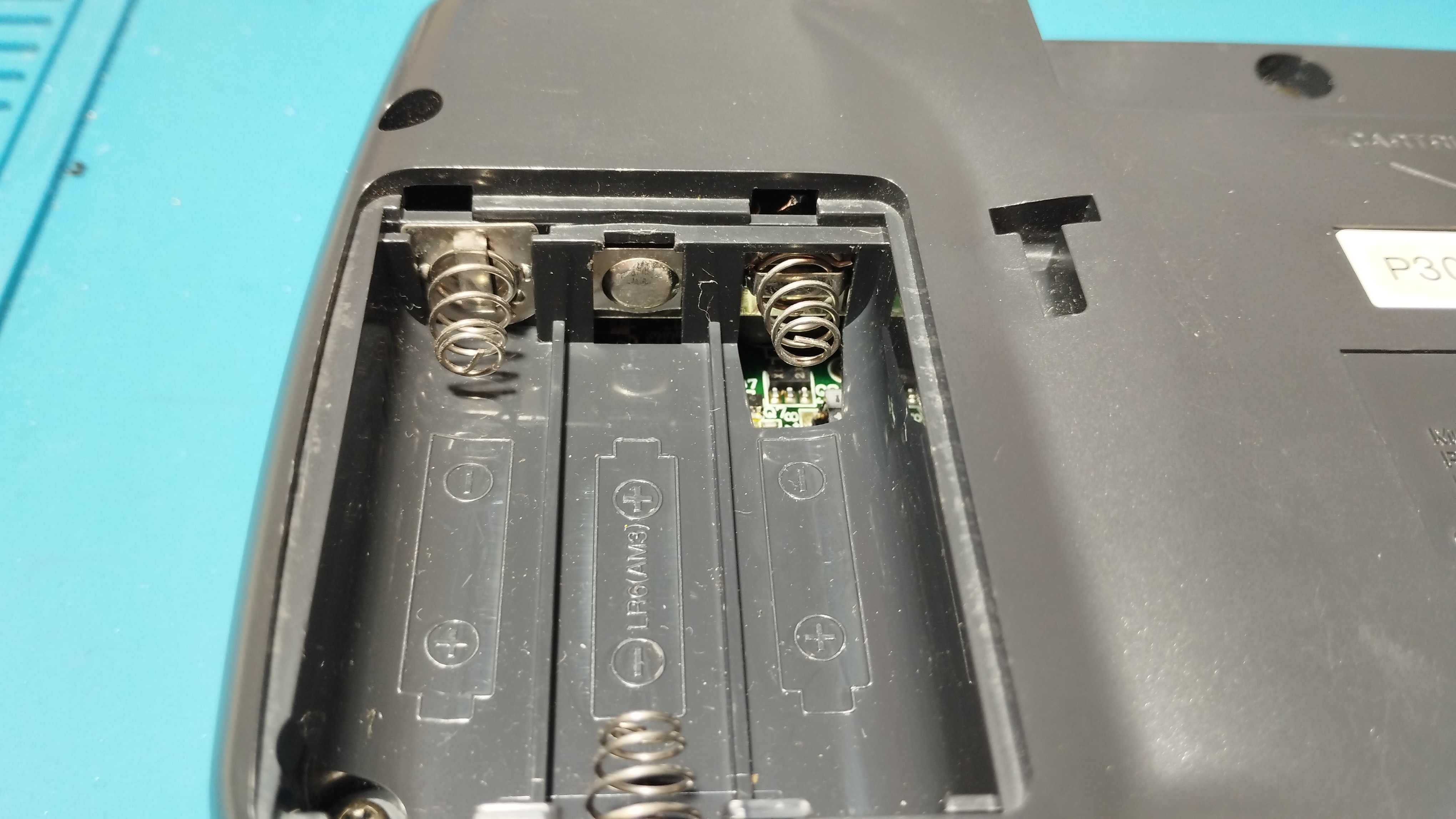
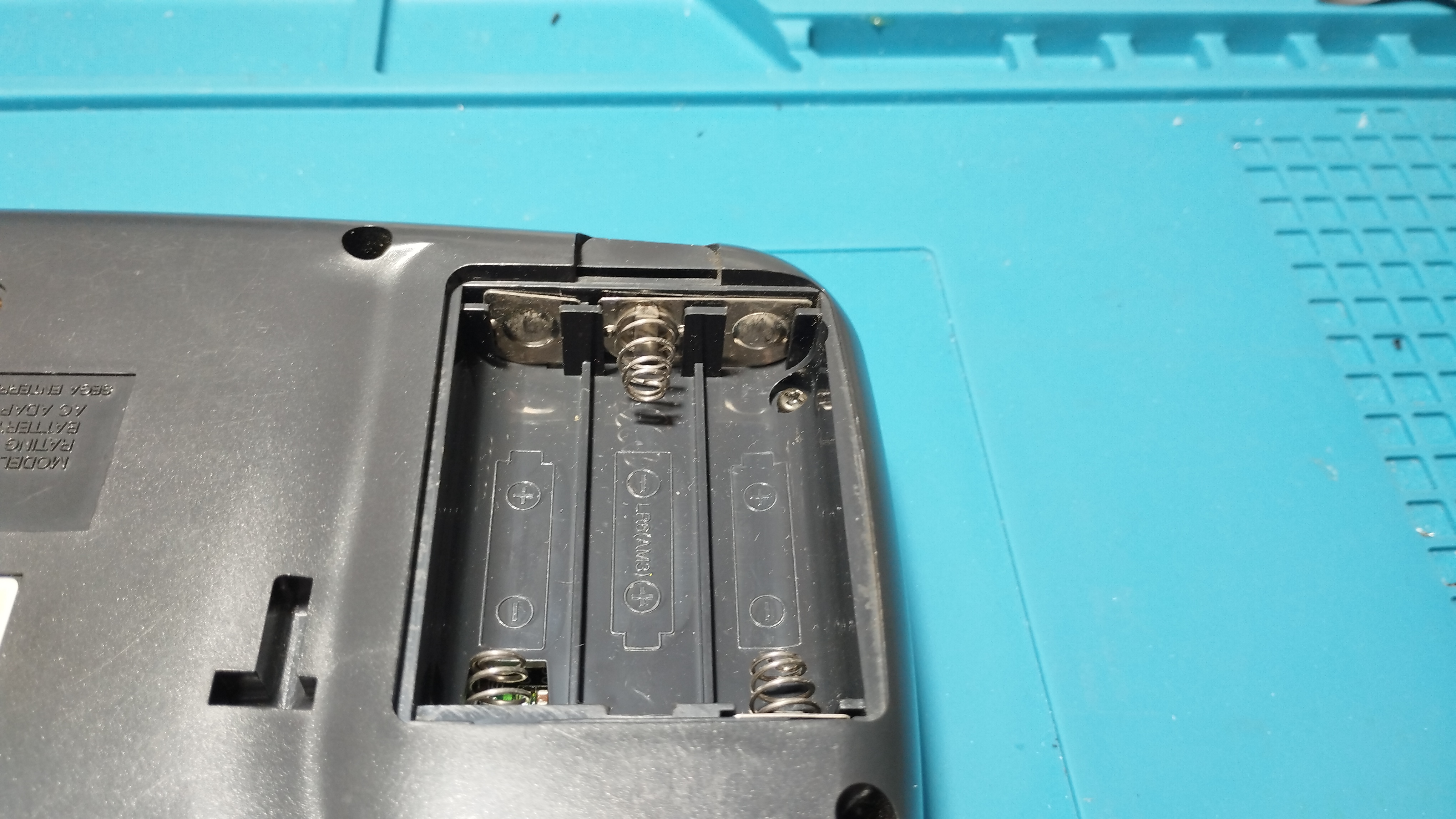
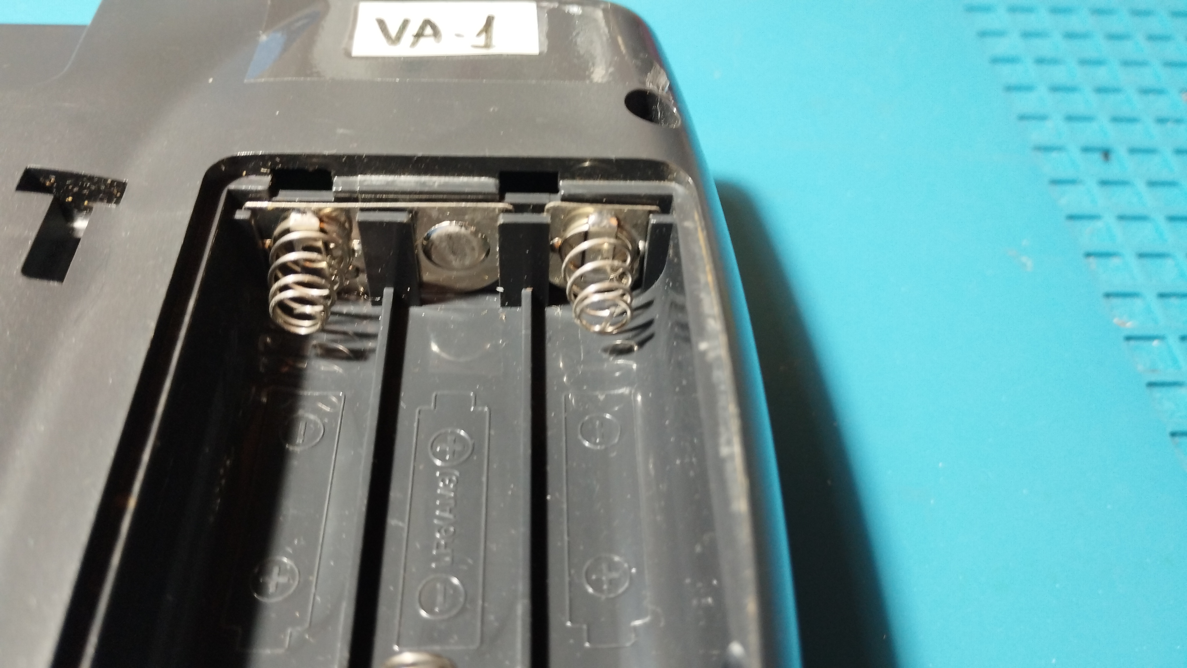
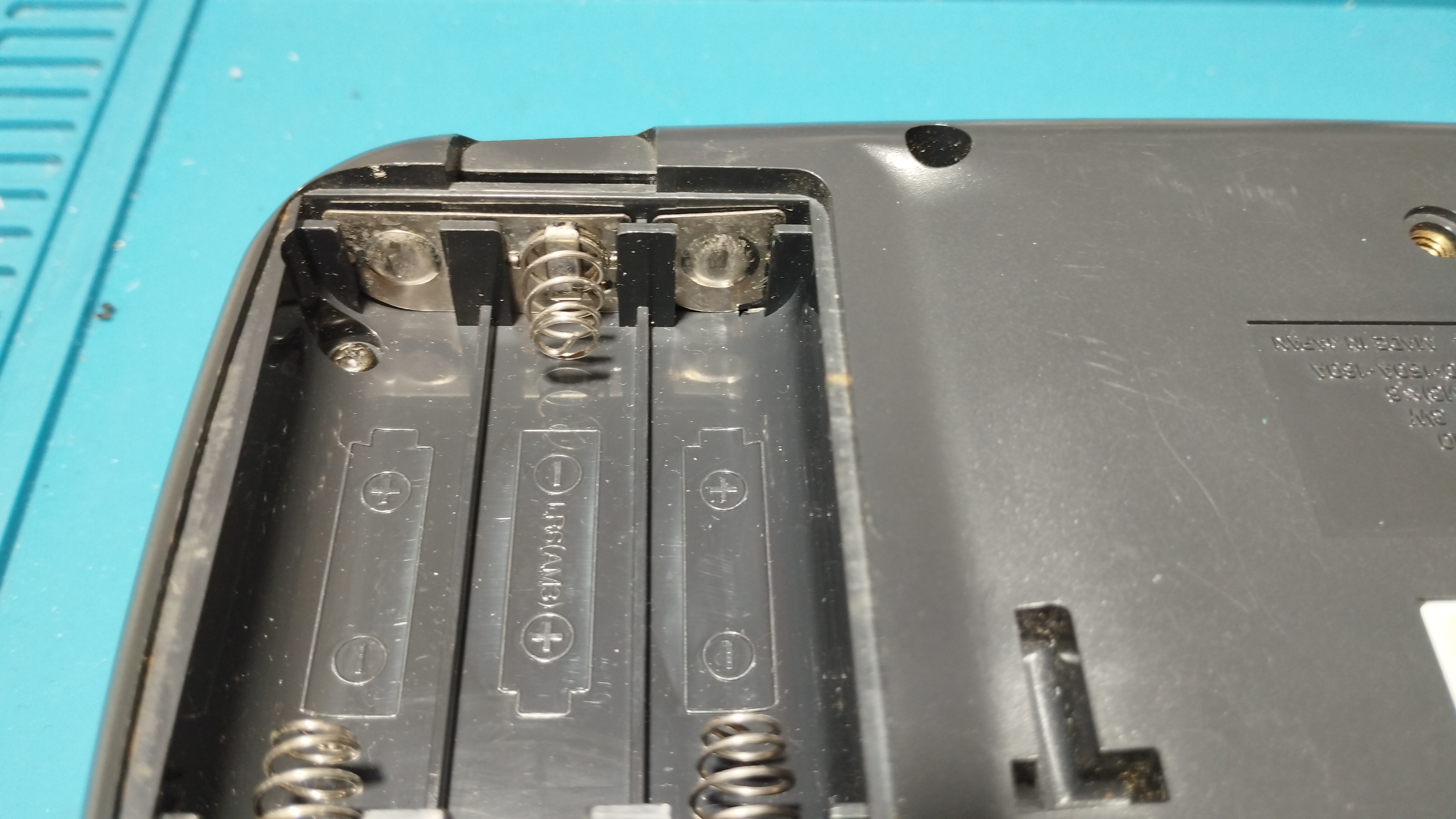
Battery contacts
No visible corrosion in battery contacts:
Maintenance
2026/04/09: Recap
Following Retrosix’s wiki, the capacitors are replaced like this:
Removing some capacitors proved to be quite challenging, even with an electrical desoldering pump. The trick to keep the vias intact is to reapply new solder several times to mix old solder with new one. Flux is indispensable to help transfer heat on already old and dry solder as well!
If a leg is stubbornly stuck, use some desoldering wick with new solder and a lot of flux to remove the excess inside the via by capilarity. Rinse and repeat until the leg is free!
Also use the desoldering wick to free the hole from solder before putting the new capacitors.
Audio board
- Before removing the capacitors, its leakage is neutralized with white vinegar diluted in water; after that, everything is properly cleaned with Isopropyl Alcohol
- All capacitors are replaced with 100uF/10V ceramic capacitors
- After recapping, the audio board works again but sound starts crackling when volume is above half its max value
Removing these surface-mount capacitors without proper care can damage the underlying pads and vias. The trick to keep the pads intact is to reapply new solder to mix old solder with new one. Flux is indispensable to help transfer heat on already old and dry solder as well!
Snap the capacitors with help of a pair of pliers, gently twisting the head back and forth. You can also cut the head to avoid applying too much stress on the pads.
Operation verification
All verifications except battery ones are done with a SEGA Mega Drive power supply (Model no. 1602-18, 10V - 1.2A).
Red Light Boot state
- Console enters the Red Light Boot state, required for further troubleshooting and repairs
Audio
- Audio board works, both the speaker output and the output jack, but sound starts to crack when volume is above half its max value
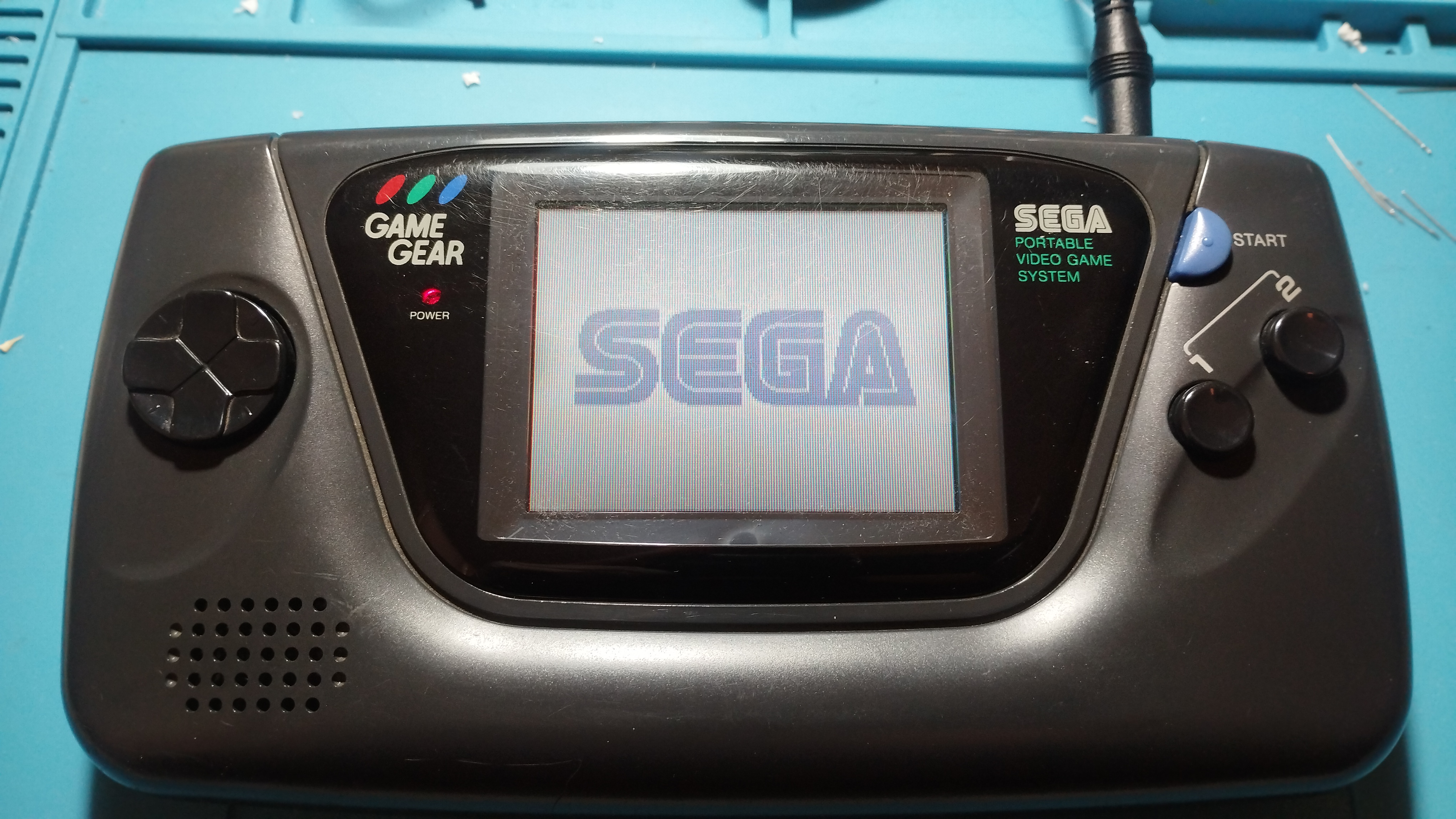
Screen
- LCD screen turns on and the fluorescent tube lights up.
- Brightness can’t be adjusted with the Bright wheel
- The game image is very dim but shows that the game runs and that the display isn’t broken
Repairing time
- 1 hour
2026/04/10: Recap
Power board
- Capacitors are replaced with new electrolytic ones with the same rating
- The only exception is the 820uF/6.3V one that has been replaced with a solid electrolytic capacitor of the same rating (does it make any difference compared to the standard electrolytic ones?)
- According to the data sheet, solid electrolytic capacitors have a low ESR and high ripple current
⚠️ TODO: Add picture of power board recapped

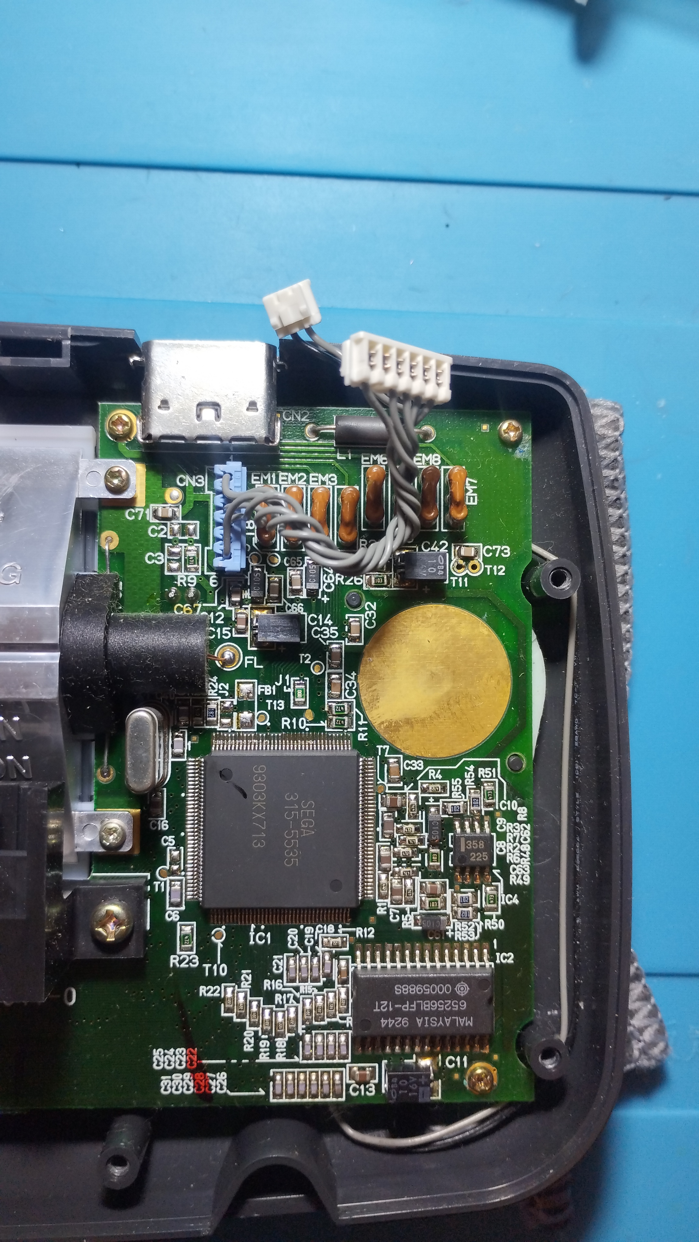
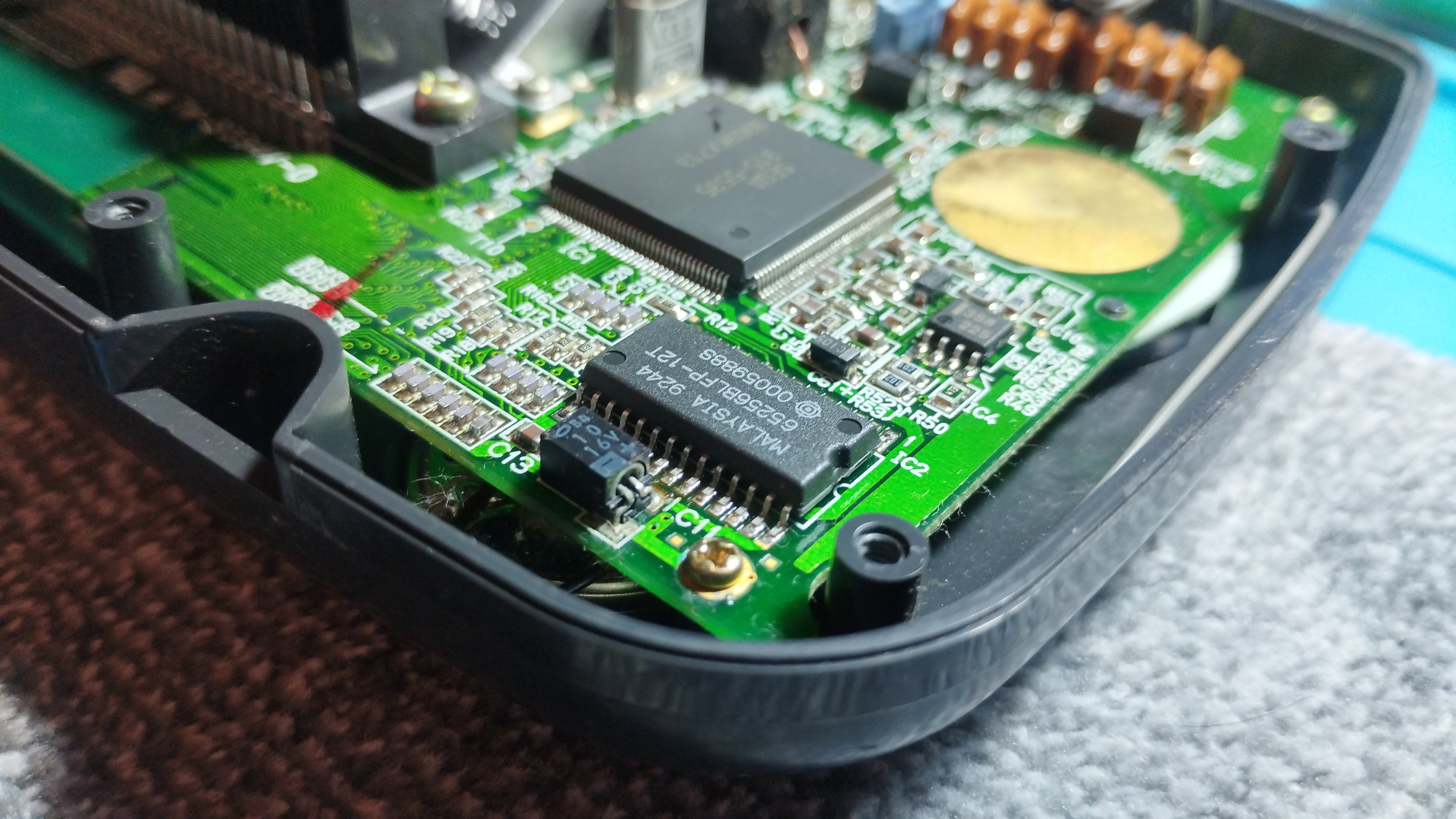
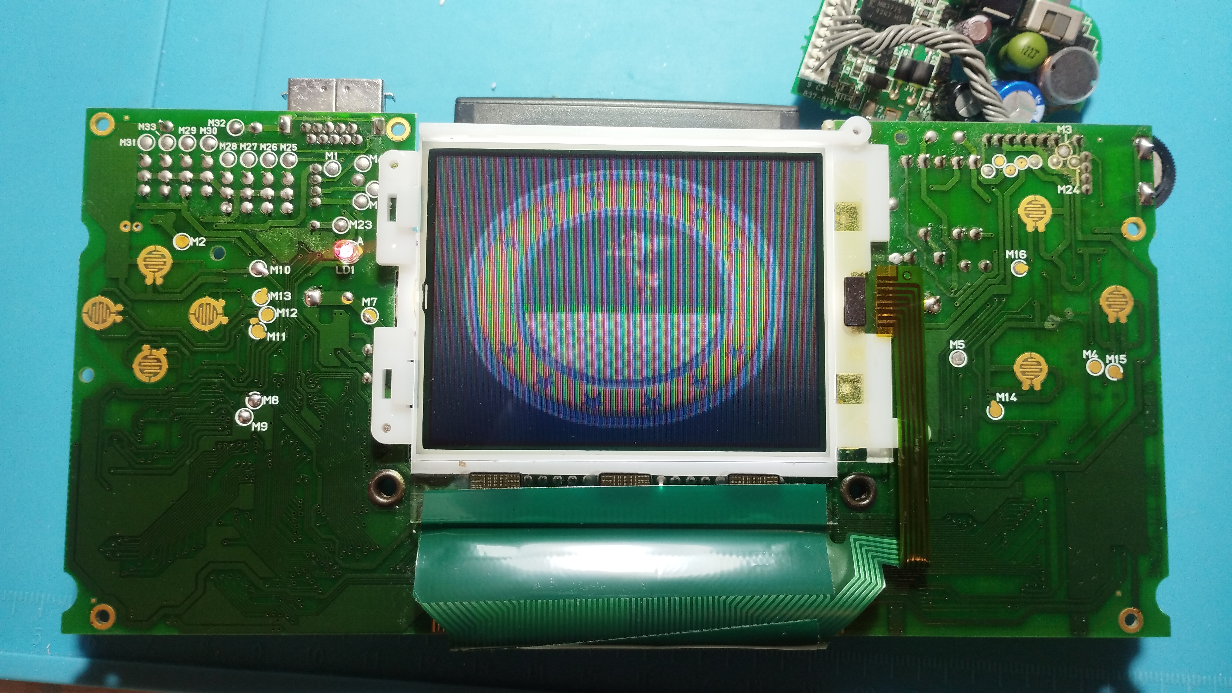
Main board
Following RetroSix Wiki advises, all capacitors have been first removed and then checked if the console reaches the Red Light Boot (RLB) state:
Components Needed for RLB
It’s worth noting that audio ICs, every aluminium capacitor, the LCD, MPU, Work RAM nor Video RAM or main crystal are involved or even needed to be soldered on the board to get to red light boot. Don’t waste your time on those until you get red light.
Prior to dettach the capacitor from the board, use the desoldering wick to remove as much solder as possible between the pad and the capacitor leg. This will help reduce mechanical stress on the pad when snapping the glue beneath the capacitor.
You can also snap the capacitors’ legs with some pliers to detach it from the board and apply less mechanical stress to the pads. Then, soak the pads with white vinegar diluted with water and clean it with Isopropyl Alcohol; once done, apply new solder to the pads and remove it again alongside the remaining capacitor legs with the solder wick.
With the capacitors removed, both power board and audio board are re-connected and the console is powered up again:
- Power LED turns on and keeps lighted up
- Fluorescent tube also lights up
- Audio also works when putting a cartridge
Once verified that the console reaches the RLB state, it’s time to solder the new capacitors. As with the previous VA-0 B0126683, these are the ceramic capacitors characteristics:
- All original capacitors rated lower than 1uF are replaced with 1uF/50V ceramic capacitors
- All original capacitors rated lower between 1uF and 10uF are replaced with 10uF/50V ceramic capacitors
- All original capacitors rated higher than 10uF are replaced with 100uF/10V ceramic capacitors
⚠️ TODO: add picture of fully recapped board

- C31 capacitor is always hard to deal with and the power connector has melted a little bit, but with the desolder wick trick the pads were intact after removal
⚠️ TODO: add picture of fully recapped board, left side detail

- The rest of the left side capacitors didn’t present any issue when removing and replacing them, and the result is pretty clean
⚠️ TODO: add picture of fully recapped board, left side detail 2

⚠️ TODO: add picture of fully recapped board, right side detail

The soldering technique used this time consisted on the following steps:
- Tin one of the pads
- Pin one side of the capacitor to that pad
- After that apply solder to the other side
- Once done, rework the first pad by applying additional solder and adjusting the capacitor by applying heat to both pads if necessary
- Use a pair of tweezers to secure the capacitor in place while applying heat
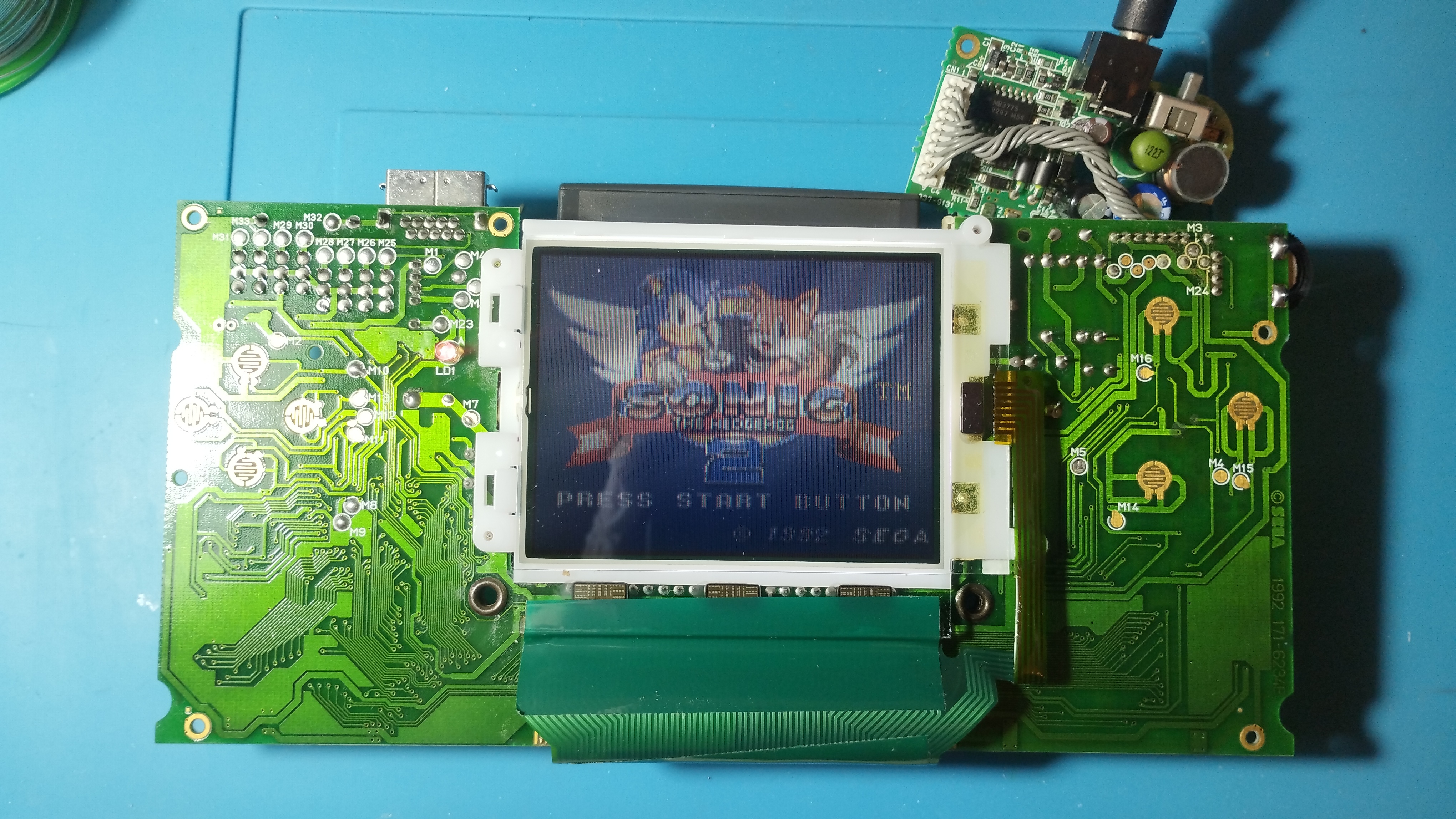
State on stable boot
- Console enters the Red Light Boot state, required for further troubleshooting and repairs
- Voltage levels are slightly higher than the ones specified in the previous Wiki, but the console run games without issues
- Audio board also works, both the speaker output and the output jack, although the sound cracks when pumped up above half its max range
- Screen flickers and dims down randomly, even resetting the console sometimes. It happens with both original cartridges and flashcarts, corrupting game flashes and returning several different error codes
- This happens when using either a power adapter or batteries
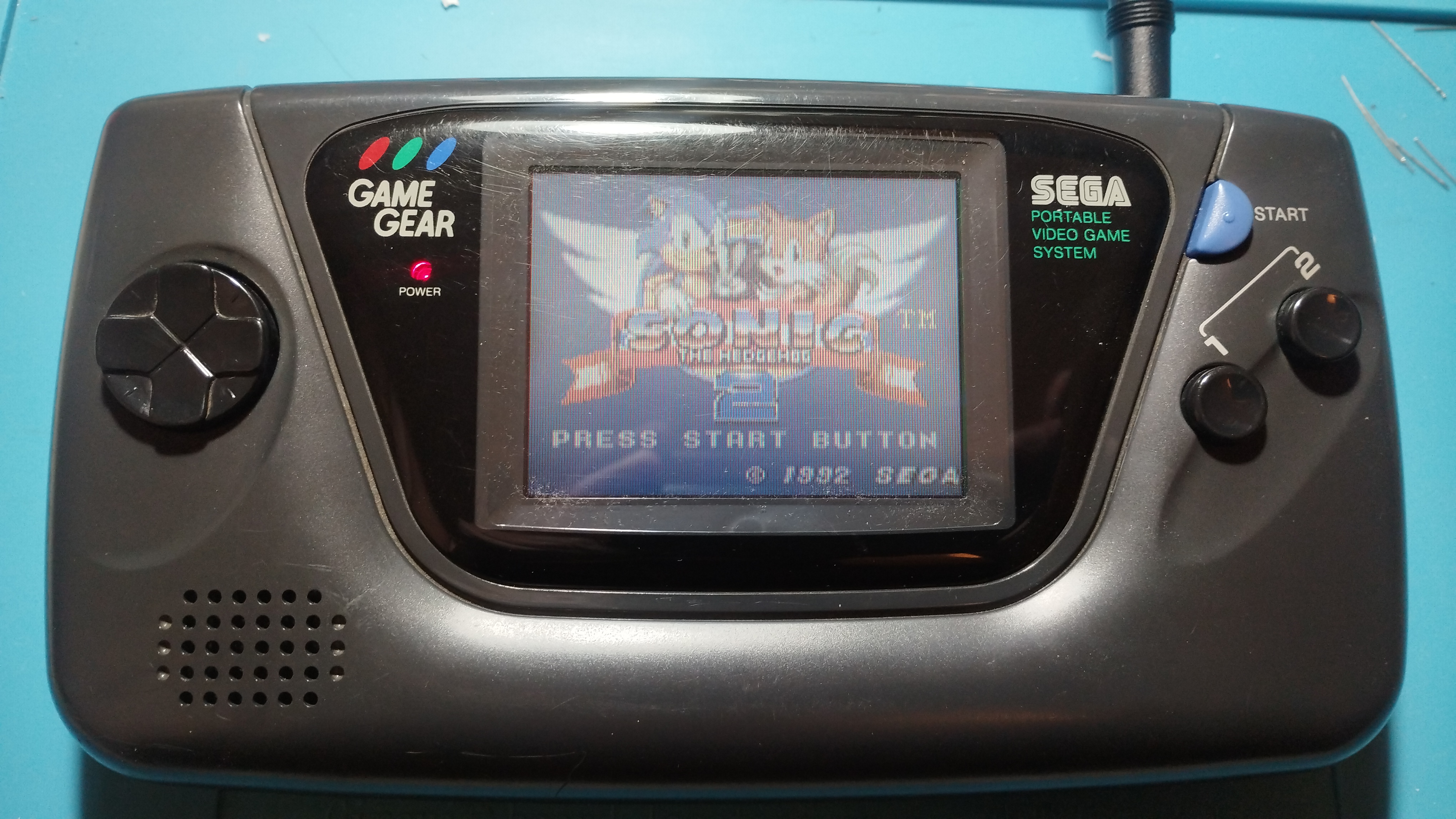
Reassembly
Console is reassembled and tested again

Repairing time
- 3 hours 30 min
Next steps
- Check audio board again for crackling sound. Test another working audio board to see if the issue is in the main board
- Check power circuit in both power board and main board. A bad trace or component might be causing the screen flickering
- Also check brightness wheel status, see if it is also the cause of the screen flickering
For preservation purposes only
This is the best Game Gear in terms of original screen so far, so unless a major issue arises, this unit shall be preserved as is, without mods.